




Choosing the right PCB board material starts with understanding how each substrate behaves in real production and real operating conditions. FR-4 may be enough for a simple control board, but a high-speed server backplane, RF antenna module, automotive battery system, LED lighting board or flexible wearable device may need a very different material structure.
This guide explains the characteristics of common PCB materials, including FR-4, high-Tg FR-4, Rogers, PTFE, polyimide, metal core, ceramic and HDI-compatible materials. It then shows how to choose a suitable PCB material based on electrical performance, thermal demand, reliability requirements, manufacturing process, cost and application environment.
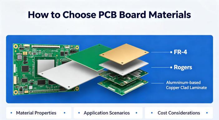
What Are PCB Board Materials?
PCB board materials are the insulating, conductive and protective materials used to build a printed circuit board. A typical PCB includes copper foil, dielectric substrate, resin system, glass reinforcement, solder mask and surface finish. Together, these layers support components, route electrical signals, manage heat and protect the circuit from environmental stress.
In engineering terms, PCB material is not just a mechanical carrier. It directly affects impedance control, signal loss, current capacity, thermal expansion, soldering reliability, warpage, via reliability and long-term field performance. This is why material selection should be discussed early, ideally before the stack-up and layout are finalized.
Why PCB Material Selection Matters
PCB material selection matters because the board must survive both manufacturing and end-use conditions. During fabrication and assembly, the material experiences drilling, lamination, plating, solder mask curing, surface finishing and reflow soldering. During product use, it may face heat, vibration, humidity, current load, high-speed signals or repeated bending.
A material mismatch can cause practical problems such as delamination, impedance drift, signal attenuation, copper cracking, via failure, board warpage, poor heat dissipation or unstable electrical performance. In mass production, even a small material mistake can create yield loss, delayed delivery and costly field returns.
Common PCB Board Materials and Their Characteristics
Different PCB board materials solve different engineering problems. FR-4 is popular because it is affordable and easy to manufacture. High-Tg FR-4 improves thermal stability. Rogers and PTFE materials support RF and microwave performance. Polyimide enables flexible and rigid-flex circuits. Metal core materials improve heat dissipation. Ceramic materials support harsh thermal environments. HDI-compatible laminates support fine lines, microvias and compact designs.
| PCB Material | Main Characteristics | Typical Applications | Key Limitations |
|---|---|---|---|
| FR-4 | Cost-effective, stable, widely available, good insulation and mechanical strength | Consumer electronics, industrial control boards, general PCBs | Limited for very high-frequency, high-heat or ultra-high-speed designs |
| High-Tg FR-4 | Better heat resistance, improved dimensional stability, suitable for multilayer boards | Automotive electronics, industrial equipment, lead-free assembly | Higher cost than standard FR-4 |
| Rogers / PTFE | Low dielectric loss, stable dielectric constant, excellent RF performance | 5G modules, radar, antennas, RF circuits, microwave boards | Higher material cost and more demanding fabrication process |
| Polyimide | Flexible, thin, heat-resistant, suitable for dynamic and compact structures | FPC, rigid-flex PCB, wearables, cameras, medical devices | Bending radius and copper fatigue must be controlled |
| Metal Core | Excellent heat dissipation and strong thermal path | LED lighting, power modules, motor control, automotive lighting | Less flexible for complex multilayer routing |
| Ceramic | High thermal conductivity, high-temperature resistance, stable electrical behavior | Power electronics, aerospace electronics, high-reliability modules | Higher cost and specialized manufacturing requirements |
| HDI-Compatible Laminates | Support fine lines, microvias, thin dielectrics and high-density routing | Smartphones, wearables, medical devices, AI modules, compact electronics | Requires tighter stack-up, lamination and drilling control |
FR-4 PCB Material: The Standard Choice for General Electronics
FR-4 is the most widely used PCB board material. It is made from woven fiberglass cloth and epoxy resin, providing a practical balance of insulation, mechanical strength, manufacturability and cost. For many products, including smart home devices, consumer electronics, power adapters, industrial modules and standard control boards, FR-4 remains the first material to consider.
The main advantage of FR-4 is its mature supply chain and stable processing window. It supports single-sided, double-sided and multilayer PCB fabrication. However, standard FR-4 is not the best option for very high-frequency RF circuits, high-speed signal channels, harsh thermal cycling or products exposed to long-term high temperature.
High-Tg FR-4: Better Heat Resistance for Reliable Multilayer Boards
High-Tg FR-4 is an upgraded FR-4 material designed for improved thermal stability. Tg means glass transition temperature, which is the point where the resin system begins to move from a rigid state toward a softer state. A higher Tg helps the PCB maintain dimensional stability during soldering, reflow and thermal cycling.
High-Tg FR-4 is commonly used in automotive electronics, industrial control systems, multilayer PCBs, power control boards and products assembled with lead-free soldering processes. It is often selected when standard FR-4 may create risks such as delamination, warpage or weak via reliability under heat stress.
Rogers and PTFE PCB Materials for High-Frequency and RF Applications
Rogers, PTFE and similar high-frequency PCB materials are used when signal loss and dielectric stability are critical. Compared with standard FR-4, these materials usually provide lower loss tangent, more stable dielectric constant and better performance at RF, microwave and millimeter-wave frequencies.
These materials are commonly found in 5G communication modules, radar systems, antennas, RF front-end circuits, satellite communication, microwave sensors and high-frequency test equipment. The trade-off is cost and process complexity. PTFE-based materials can require special drilling, surface preparation and lamination control, so early communication with the PCB manufacturer is important.
Polyimide PCB Material for Flexible and Rigid-Flex Circuits
Polyimide is widely used in flexible PCBs and rigid-flex PCBs because it is thin, flexible and heat-resistant. It allows the PCB to bend, fold or fit into compact mechanical spaces where a rigid board would be too large or too fragile.
Polyimide materials are common in wearables, cameras, medical electronics, foldable devices, sensors, automotive interiors and compact consumer products. When choosing polyimide, engineers should pay close attention to bend radius, copper thickness, adhesive type, stiffener design and whether the flex area is static or dynamic during product operation.
Metal Core PCB Materials for LED, Power and Thermal Management
Metal core PCB materials use aluminum, copper or another metal base to improve heat dissipation. Instead of keeping heat trapped near components, the metal base helps spread and transfer heat away from LEDs, power devices and high-current components.
Aluminum PCBs are widely used in LED lighting because they offer good thermal performance at a practical cost. Copper base PCBs provide stronger heat dissipation but are usually more expensive. Metal core boards are useful for automotive lighting, power modules, motor drivers and charging equipment, but they are less convenient for dense multilayer signal routing.
Ceramic PCB Materials for High Thermal Conductivity and Harsh Environments
Ceramic PCB materials are selected for applications that need high thermal conductivity, strong insulation and stable performance under high temperature. Common ceramic substrates include alumina and aluminum nitride, depending on thermal and electrical requirements.
Ceramic PCBs are used in power electronics, high-reliability modules, aerospace electronics, semiconductor-related equipment and harsh-environment applications. They are not usually chosen for low-cost general electronics because material and processing costs are higher, but they can be valuable when thermal performance and reliability outweigh cost concerns.
HDI PCB Materials for Compact and High-Density Electronics
HDI PCB materials are used for high-density interconnect boards that require fine lines, small vias, microvias, blind vias, buried vias and thin dielectric layers. The material must support stable lamination, laser drilling, copper plating and dimensional control across multiple build-up cycles.
HDI materials are common in smartphones, wearables, medical devices, AI modules, compact communication devices, cameras and miniaturized industrial electronics. The key is not only the laminate itself, but also the full stack-up design, via structure, copper thickness and manufacturing capability.
Key PCB Material Properties to Compare Before Selection
Before choosing a PCB material, engineers should compare the properties that affect performance and manufacturing yield. The most important parameters include dielectric constant, loss tangent, Tg, CTE, thermal conductivity, copper thickness, moisture absorption, flammability rating and compatibility with the required surface finish.
| Property | Why It Matters | Common Design Concern |
|---|---|---|
| Dielectric Constant | Affects impedance and signal propagation speed | High-speed digital and RF performance |
| Loss Tangent | Controls signal attenuation at high frequency | Insertion loss and signal integrity |
| Tg | Indicates thermal stability of the resin system | Lead-free soldering and thermal cycling |
| CTE | Shows how much the material expands with temperature | Via cracking, layer stress and warpage |
| Thermal Conductivity | Determines how well heat moves through the board | LED, power electronics and high-current boards |
| Moisture Absorption | Affects insulation resistance and reflow reliability | Delamination, CAF risk and long-term reliability |
| Copper Thickness | Controls current capacity and heat generation | Power boards, battery systems and motor control |
How to Choose the Right PCB Board Material
The right PCB material should be chosen by matching the material to the real operating conditions of the product. Start with the electrical requirements. If the design is a standard digital or low-frequency circuit, FR-4 may be enough. If the board carries RF, microwave or very high-speed signals, low-loss materials should be reviewed.
Next, check the thermal and mechanical requirements. High-temperature products may need high-Tg FR-4, ceramic or special laminates. High-current and LED applications may need metal core or thick copper boards. Products with bending or folding requirements usually need polyimide flexible or rigid-flex structures.
Finally, compare production volume, budget and availability. A high-performance material may look attractive on paper, but if it increases lead time, reduces yield or exceeds the product cost target, it may not be the best choice. A manufacturable material is usually more valuable than an over-specified one.
PCB Material Selection by Application
A practical way to choose PCB board materials is to start from the application. Different industries have different priorities. Consumer electronics often focus on cost and compact design. Automotive electronics require reliability and thermal cycling resistance. Communication systems need controlled impedance and low signal loss. LED and power boards focus heavily on heat dissipation.
| Application | Recommended PCB Material | Why It Is Used | Key Risk to Check |
|---|---|---|---|
| General consumer electronics | Standard FR-4, HDI, FPC | Cost-effective, compact and widely supported | Thin board warpage and assembly yield |
| Automotive electronics | High-Tg FR-4, thick copper, metal core, HDI | Improves thermal cycling, vibration resistance and reliability | Material must match long-term reliability requirements |
| Communication equipment | Low-loss FR-4, Rogers, PTFE, high-layer-count laminates | Supports impedance control and high-speed signal transmission | Insertion loss, dielectric stability and stack-up tolerance |
| AI servers and data centers | Low-loss high-speed laminates, high-layer-count materials | Supports fast signals, dense routing and strict impedance control | Material availability, lamination control and cost |
| Industrial control | High-Tg FR-4, thick copper, multilayer FR-4 | Balances durability, cost and stable production | EMC, thermal stress and long service life |
| Medical electronics | HDI, rigid-flex, high-reliability FR-4, special laminates | Supports compact design, signal stability and reliability | Traceability, process control and compliance needs |
| LED lighting | Aluminum PCB, copper base PCB, metal core PCB | Improves thermal transfer from LEDs to heat sink | Thermal conductivity and dielectric breakdown strength |
| Power electronics | Thick copper, metal core, ceramic, high-Tg FR-4 | Handles current, heat and voltage stress | Creepage, clearance, copper balance and heat rise |
How to Choose PCB Materials for High-Speed and RF Designs
For high-speed and RF PCBs, material selection should focus on dielectric constant stability, loss tangent, copper roughness, impedance tolerance and stack-up repeatability. Standard FR-4 can work for many moderate-speed designs, but it may become unreliable when signal frequency increases or insertion loss becomes critical.
Rogers, PTFE and low-loss laminates are often selected for RF, microwave, antenna, radar and advanced communication products. For digital high-speed designs, the choice may depend on channel length, data rate, layer count and allowed insertion loss. The safest approach is to confirm the stack-up with the PCB manufacturer before final routing.
How to Choose PCB Materials for Automotive and Industrial Electronics
Automotive and industrial electronics usually require stable performance under temperature change, vibration, humidity and long operating life. Materials should be selected with attention to Tg, CTE, copper thickness, insulation resistance and compatibility with reliability testing.
High-Tg FR-4 is often a practical choice for automotive control boards, industrial automation modules, motor control and power management circuits. Thick copper and metal core materials may be needed when current and heat are major concerns. For compact automotive electronics, HDI or rigid-flex structures may also be used.
How to Choose PCB Materials for LED and Power Electronics
LED and power electronics generate heat, so thermal performance is often more important than routing density. Aluminum PCB and copper base PCB materials provide a more direct thermal path than standard FR-4. Thick copper can also help carry current and reduce heat rise in power traces.
When selecting materials for power boards, engineers should review current capacity, voltage spacing, insulation thickness, dielectric strength, thermal conductivity and copper weight. The board design should avoid local hot spots, unbalanced copper distribution and insufficient clearance between high-voltage nets.
Common PCB Material Selection Mistakes
One common mistake is choosing a material only by price. A low-cost material can become expensive if it causes poor yield, rework, field failure or delayed shipment. Another mistake is over-specifying the material. Using an RF laminate for a simple low-speed control board may add cost without real benefit.
Engineers should also avoid copying a material from a previous project without checking the new operating conditions. Board thickness, copper weight, component heat, layer count, reflow profile and enclosure design can all change material performance. A good material decision is always connected to the full product design, not just the PCB drawing.
PCB Material Cost Factors
PCB material cost depends on laminate type, copper thickness, board thickness, layer count, special dielectric requirements, high-frequency performance, thermal conductivity, HDI process, surface finish and production volume. Standard FR-4 is usually the most economical option, while Rogers, PTFE, ceramic and complex rigid-flex materials can increase cost.
Cost should be reviewed together with manufacturability. A slightly better material may reduce yield risk in mass production, while an unnecessary premium material may make the product less competitive. For OEM and ODM projects, early material review can help balance performance, lead time and total production cost.
Quality Standards and Testing for PCB Materials
Reliable PCB material selection should be supported by recognized standards and process control. Common references include IPC material specifications, UL safety requirements, RoHS compliance and customer-specific reliability standards. For medical, automotive and industrial products, documentation and traceability are especially important.
Practical tests may include impedance testing, thermal stress testing, solderability testing, microsection inspection, copper thickness measurement, insulation resistance testing and dimensional inspection. For high-reliability boards, material quality must be verified not only at the datasheet level but also through stable fabrication and inspection processes.
PCB Material Selection Checklist Before Manufacturing
Before releasing a PCB for prototype or mass production, review the material decision with your PCB manufacturer. The checklist below helps reduce avoidable engineering changes and production delays.
- Confirm operating temperature, current load and expected product lifetime.
- Check whether the design needs controlled impedance or low-loss material.
- Review Tg, CTE, thermal conductivity and moisture absorption.
- Confirm copper thickness, board thickness and stack-up tolerance.
- Check whether the board requires HDI, blind vias, buried vias or microvias.
- Confirm bending radius and dynamic flex requirements for FPC or rigid-flex PCB.
- Review surface finish compatibility with components and assembly process.
- Check certification requirements such as UL, RoHS, ISO 9001, ISO 13485 or IATF 16949 where applicable.
- Ask the manufacturer whether the selected material is stable for prototype and mass production.
- Compare material availability, lead time and cost before final approval.
How Thindry Supports PCB Material Selection and Manufacturing
Thindry is a China-based PCB manufacturer and assembly service provider with more than a decade of experience in PCB prototype, fabrication and PCBA assembly. By integrating PCB fabrication, component sourcing, assembly support and engineering review, Thindry helps customers move from prototype validation to stable production.
Our engineering team supports material evaluation for FR-4, high-Tg FR-4, HDI boards, flexible PCBs, rigid-flex PCBs, high-frequency boards, metal core PCBs and thick copper boards. We focus on manufacturability, cost control, quality consistency and reliable delivery for global OEM and ODM customers.
Thindry’s quality system supports international manufacturing requirements, including ISO 9001, ISO 13485, IATF 16949, UL certified PCB production and RoHS compliance. These controls help customers reduce material risk, improve production repeatability and maintain confidence from sample development to batch manufacturing.
FAQ About PCB Board Materials
What is the best material for a PCB board?
There is no single best PCB material for every design. FR-4 is the best practical choice for many standard products because it is affordable and reliable. For RF, flexible, high-temperature, high-current or compact HDI products, specialized materials such as Rogers, polyimide, high-Tg FR-4, metal core or ceramic substrates may be better.
Is FR-4 good enough for most PCB designs?
Yes, FR-4 is good enough for many standard digital, analog and control board designs. It provides a strong balance of cost, insulation, mechanical strength and manufacturability. However, it may not be suitable for very high-frequency circuits, extreme heat, demanding automotive environments or applications requiring repeated bending.
When should I choose high-Tg FR-4?
High-Tg FR-4 is recommended when the board must handle higher thermal stress, lead-free soldering, multilayer lamination, automotive use or long-term industrial operation. It improves dimensional stability and reduces the risk of thermal-related failures compared with standard FR-4.
What is the difference between FR-4 and Rogers PCB material?
FR-4 is a general-purpose material with good cost efficiency, while Rogers materials are designed for better high-frequency performance. Rogers laminates usually provide lower signal loss and more stable dielectric properties, making them suitable for RF, microwave, antenna, radar and advanced communication circuits.
What PCB material should be used for flexible boards?
Flexible boards usually use polyimide because it is thin, heat-resistant and bendable. It works well for FPC and rigid-flex PCB designs used in cameras, wearables, medical devices and compact electronics. The design must control bend radius, copper thickness, stiffener location and dynamic flex life.
What PCB material is best for LED lighting?
Metal core PCB materials, especially aluminum substrates, are commonly used for LED lighting because they transfer heat away from LEDs more efficiently than standard FR-4. Copper base materials may be used when stronger thermal performance is required, but the cost is usually higher.
How does PCB material affect signal integrity?
PCB material affects signal integrity through dielectric constant, loss tangent, copper roughness and stack-up consistency. In high-speed and RF designs, poor material selection can increase signal loss, impedance variation, reflections and timing problems. This is why low-loss materials are often used for demanding signal channels.
Does thicker copper require a different PCB material?
Thicker copper does not always require a different base material, but it does affect fabrication, heat distribution, current capacity and copper balance. For high-current designs, engineers should review copper weight, trace width, thermal rise, spacing and lamination capability before confirming the PCB material and stack-up.
What PCB material should be used for automotive electronics?
Automotive electronics often use high-Tg FR-4, thick copper, HDI, metal core or rigid-flex materials depending on the function. The key requirements are thermal cycling resistance, vibration durability, long-term reliability and stable production quality. Material selection should match the product’s operating environment and reliability target.
Can I use standard FR-4 for high-speed PCB designs?
Standard FR-4 can be used for some moderate-speed designs, especially when traces are short and loss requirements are not strict. For very high-speed channels, long transmission paths or tight insertion loss limits, low-loss FR-4 or specialized high-speed laminates are usually safer choices.
Why is ceramic PCB material more expensive?
Ceramic PCB material is more expensive because the substrate, processing methods and manufacturing control are more specialized. It is selected when high thermal conductivity, high-temperature resistance or strong electrical stability is more important than low cost. It is not usually used for ordinary consumer electronics.
How can buyers reduce PCB material cost without reducing quality?
Buyers can reduce cost by avoiding unnecessary premium materials, standardizing stack-ups, confirming material availability early and working with the manufacturer before layout is locked. The goal is not to choose the cheapest material, but to select a stable, manufacturable material that meets performance requirements.
Final Thoughts: Choosing PCB Board Materials with Lower Risk
The best way to choose PCB board materials is to understand the material characteristics first, then match them to the real application. FR-4 is suitable for many general products. High-Tg FR-4 improves thermal reliability. Rogers and PTFE support RF and microwave performance. Polyimide enables flexible and rigid-flex designs. Metal core and ceramic materials solve thermal challenges. HDI-compatible laminates support compact, high-density electronics.
For engineering teams, material selection should consider signal speed, frequency, heat dissipation, current load, bending requirements, assembly process, reliability standards and production volume. For buyers, the safest approach is to work with a PCB manufacturer that can review the design, recommend manufacturable materials and support stable prototype-to-mass-production delivery.
If you are looking for reliable OEM manufacturing, ODM production, sample development, mass production or custom engineering solutions, welcome to contact our engineering team for technical support and quotation services.



0 Comments