




Avoid the mistakes that cause loose wires, lifted pads, and hours of frustration.
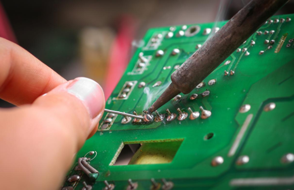
Soldering a wire to a PCB sounds simple. Heat the pad, melt some solder, stick the wire on, done.
Except it’s never that clean, is it?
Most beginners end up with a blobby gray mess that falls off the moment you breathe on it. Or they crank the heat too high and watch the copper pad peel right off the board like a sticker. Or they spend twenty minutes fighting with a multi-strand wire that keeps fraying into a tiny bird’s nest the second it touches the pad.
I’ve seen all of these more times than I can count. And here’s the thing — none of them are hard to fix once you understand what’s actually going wrong.
This guide walks you through the entire process, from picking the right tools to inspecting your finished joints. I’ll also call out the specific mistakes that trip up most people, with clear descriptions of what good and bad solder joints actually look like. Because honestly, half the battle is just knowing what you’re aiming for.
Part 1: Getting Your Setup Right — Half the Battle
Here’s something nobody tells beginners: the quality of your solder joints is largely determined before you even pick up the soldering iron. Your workspace, your tools, your prep work — that’s where success or failure starts.
The Tool List You Actually Need
You don’t need to spend a fortune to get good results. Here’s what matters and what doesn’t.
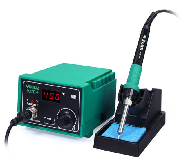
Soldering station or iron. This is the one thing worth spending a little money on. A temperature-controlled soldering station gives you consistent heat, which is the single biggest factor in getting clean joints. You don’t need a top-tier professional unit that costs hundreds of dollars. A decent adjustable station in the $40 to $80 range will do everything you need for PCB wire soldering. If you’re on a tight budget, a simple stick-style iron with adjustable temperature around $20 to $30 works too — just make sure it can actually hold temperature when it touches the board. The super cheap no-name irons that plug straight into the wall with no temperature control are where most beginners go wrong. They run too hot, they run too cold, and they fluctuate wildly depending on what you’re touching.
Solder wire. For general PCB work, 60/40 or 63/37 leaded solder in the 0.8mm diameter range is the easiest to work with. Lead-free solder is required for production work, but if you’re learning or doing hobby repairs, leaded solder flows better and forgives more mistakes. If you’re working on very fine-pitch pads, drop down to 0.5mm diameter. For bigger wire-to-pad joints on power connections, 1.0mm works fine. A 100g spool will last you a very long time.
Flux. Yes, your solder wire probably has a rosin core. No, that’s not always enough. Having a separate flux pen or a small tub of paste flux on your bench makes a noticeable difference, especially when you’re soldering to older pads or working with lead-free solder. Flux helps the solder flow, reduces oxidation, and makes the whole process more forgiving. It’s a five-dollar upgrade that changes your results dramatically.
Other essentials:
- Brass wool or a damp sponge for cleaning the tip between joints
- Isopropyl alcohol (90% or higher) for cleaning the PCB and wires before soldering
- Fine tweezers or small pliers for holding wires in place
- A PCB holder, helping hands, or even a blob of blue tack to keep the board stable
- A small brush or cotton swabs for post-soldering cleanup
- Wire strippers that match your wire gauge
What you don’t need yet: Hot air stations, microscope cameras, fancy desoldering guns, or a three-hundred-dollar soldering station. Start with the basics, get comfortable, then upgrade specific tools as your needs become clear.
Preparation: The Step Everyone Skips
Before you touch the iron to anything, do these three things:
Clean the PCB pads. Use a cotton swab dipped in isopropyl alcohol to wipe the pads where you’ll be soldering. Even brand-new boards can have a thin layer of oxidation or residual flux from manufacturing. Clean pads accept solder dramatically better than dirty ones. This takes thirty seconds and saves you real headaches.
Pre-tin your wire. This is the single most important tip in this entire article, and it’s the one most beginners skip. Strip your wire, twist the strands tight, apply a little flux, then coat the exposed wire with a thin layer of solder before you even try to attach it to the board. This is called “tinning,” and it transforms the soldering process. A pre-tinned wire transfers heat better, accepts solder faster, and stays exactly where you put it. Without tinning, multi-strand wires fray apart, single-strand wires oxidize on contact with the iron, and the whole joint becomes a frustrating fight.
Secure the board. Never try to solder on a board that’s sliding around your desk. Use a PCB holder, a set of helping hands, or even tape the board down. Stability lets you focus on the joint instead of chasing the board across the table.
Part 2: The Soldering Process — Step by Step
Once your prep is done, the actual soldering follows a specific sequence. Don’t reorder these steps. Each one exists for a reason.
Step 1: Set your temperature. For leaded solder, somewhere between 315 and 370 degrees Celsius (600 to 700 Fahrenheit) works well for most PCB wire joints. Lead-free solder needs a bump — around 370 to 400 Celsius. If you’re using a basic iron without temperature display, you’ll need to learn the feel: if solder takes more than two or three seconds to melt on contact with the tip, it’s too cold. If it melts instantly and produces a lot of smoke and sizzling, it’s too hot.
Step 2: Clean the tip. Wipe the iron tip on brass wool or a damp sponge. You want a bright, shiny tip — not a blackened, crusty one. A dirty tip won’t transfer heat properly, no matter how hot the iron is.
Step 3: Apply flux to the pad. Even if your solder has a flux core, a small dab of extra flux on the pad makes a real difference. It helps the solder flow evenly and bond properly to the copper.
Step 4: Heat the pad, not the solder. This is where most people go wrong. Touch the iron tip to the pad and the wire at the same time. Wait a second or two for the pad to come up to temperature. Then feed the solder into the joint — not onto the iron tip, but into the point where the pad, wire, and iron tip all meet. You’ll see the solder flow outward and coat the pad evenly. That’s what you want.
Step 5: Remove the solder, then the iron. Pull the solder wire away first, then lift the iron. The whole process from iron contact to iron removal should take roughly three to five seconds for a standard through-hole pad. If it takes longer, something is wrong — usually insufficient heat or a dirty tip.
Step 6: Don’t touch anything. Hold still. Let the joint cool naturally for a few seconds. Moving the wire while the solder is still liquid creates what’s called a “cold joint” — the solder looks dull and grainy, and the electrical connection is unreliable.
Part 3: What Good and Bad Solder Joints Actually Look Like
This is the section that most soldering guides skip, and it’s honestly the most useful part. Knowing what a good joint looks like versus a bad one gives you a self-check tool you can use every single time.
A good solder joint:
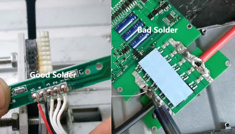
Think of the letter V. A properly soldered wire-to-pad joint has a smooth, slightly concave shape — the solder fans out from the wire base to the pad edges in a gentle slope. The surface is shiny (for leaded solder) or has a slight satin sheen (for lead-free). The copper pad is visible underneath the solder fillet around the edges. You can see that the solder actually wetted to both the pad and the wire — it didn’t just sit on top like a ball. The wire strands are completely hidden under solder, with no bare copper poking through.
A cold joint:
The solder looks dull, grainy, or lumpy. Instead of a smooth cone shape, it forms a rounded blob that sits on the pad without actually flowing onto it. You might see visible wire strands poking through the solder. The surface looks rough, almost like the solder froze mid-flow. These joints have poor electrical conductivity and will crack under mechanical stress. The fix is simple: reheat with the iron and let the solder flow properly.
An overworked joint:
The pad looks burned or discolored. The solder has a dull, oxidized surface. There might be charred flux residue around the joint. The board substrate might be slightly warped or browned underneath. This happens when you leave the iron on too long or reheated the joint too many times. In mild cases, the joint still works electrically. In severe cases, the pad delaminates from the board and you’ve got a much bigger problem on your hands.
A solder bridge:
This is when solder flows from one pad to an adjacent pad, creating an unintended short circuit. It looks like a single blob of solder spanning two separate pads. This is especially easy to do on boards with tight pad spacing. If you catch it while the solder is still molten, a quick touch with a clean tip usually clears it. If it’s already solid, use solder wick or a desoldering braid to remove the bridge.
Excess solder:
The joint looks like a big shiny ball sitting on top of the pad. You can’t see the pad edges underneath, and the wire just disappears into a round lump. While this joint might work electrically, it hides potential problems underneath — you can’t visually confirm that the solder actually bonded to the pad. The fix is to reheat and wick away the excess with solder wick.
The takeaway: After every joint, spend two seconds looking at it. If it doesn’t match the description of a good joint, fix it now while everything is still clean and accessible. Finding a bad joint after you’ve moved on to the next ten connections is much more annoying.
Part 4: The 5 Mistakes That Ruin Otherwise Good Solder Joints
If your joints aren’t turning out right, one of these is almost certainly the culprit.
Mistake 1: Wrong temperature. Too cold and the solder won’t flow — it just forms a blob on top of the pad and refuses to wet. Too hot and you’ll burn the flux before it can do its job, oxidize the solder, damage the pad, or even lift the copper right off the board. The sweet spot for leaded solder is 315 to 370 Celsius. If your joints consistently look dull or grainy, try bumping the temperature up by about fifteen degrees.
Mistake 2: Skipping flux. Solder core flux works okay for fresh, clean joints. But for anything else — reworking an old joint, soldering to an oxidized pad, or working with lead-free solder — extra flux makes an enormous difference. It’s the difference between solder that balls up and refuses to stick, and solder that flows smoothly onto the pad like it belongs there. Get a flux pen and keep it on your bench.
Mistake 3: Too much or too little solder. Too much and you get a big ball that hides the joint and might bridge to adjacent pads. Too little and the wire is barely held — mechanical stress will snap it right off. You’re looking for a smooth fillet that covers the pad and completely encases the wire, with the pad edges still visible around the outside. When in doubt, err on the side of less. You can always add more.
Mistake 4: Moving before it’s cool. The solder needs three to five seconds to solidify after you remove the iron. If you bump the wire or flex the board during this window, the internal crystal structure of the solder gets disrupted. The result is a cold joint — it might look okay on the surface, but it’s mechanically weak and electrically unreliable. Just hold still for a few seconds. It’s a small thing that makes a big difference.
Mistake 5: Heating the wire instead of the pad. This is a subtle one. If you touch the iron to the wire and feed solder at the wire, the solder might coat the wire nicely — but never actually bond to the pad underneath. The joint looks okay from the side, but there’s no real connection to the board. Always heat the pad and wire simultaneously, and feed the solder into the joint where all three elements meet.
Part 5: Different Wires, Different Approaches
Not all wire-to-PCB joints are the same. The technique shifts depending on what you’re working with.
Multi-strand wire for signal connections. These thin, flexible wires are the most common in hobby electronics and prototyping. The key challenge is keeping the strands together. Pre-tinning is absolutely essential here — apply flux, coat the stripped end with solder, and twist while the solder is molten to lock the strands into a single solid pin. After tinning, the wire behaves like a solid conductor and is much easier to work with.
Thicker power wires. Power connections often use heavier gauge wire that needs to carry significant current. These joints require more heat because the thicker wire acts as a heat sink, pulling warmth away from the joint. You may need to bump your iron temperature up slightly, or spend an extra second or two heating before feeding solder. Make sure the solder flows all the way around the wire and fully wets the pad. A partially bonded power wire is a fire hazard waiting to happen.
Ribbon cables and fine-pitch connections. When you’re attaching multiple wires to closely spaced pads, precision becomes critical. Use thinner solder (0.5mm), apply flux to all pads before you start, and work one joint at a time. If the pads are very close together, consider soldering every other pad first, then coming back for the remaining ones. This gives each joint space to cool without disturbing its neighbor.
Stranded wire that keeps fraying. If your wire keeps splitting apart and you can’t get all the strands onto the pad, stop fighting it and pre-tin first. Strip the wire, twist the strands clockwise as tight as you can, apply flux, and tin with a generous amount of solder. Let it cool into a solid pin. If strands are still poking out, clip them with flush cutters. A clean, tinned wire end is ten times easier to solder than a frayed one.
Part 6: Testing and Finishing
You’ve made the joint. It looks good. But before you call it done, run through these checks.
Visual inspection. Look at the joint under good lighting or magnification if you have it. Check for the characteristics described above — smooth fillet, visible pad edges, no bridges to nearby pads, no grainy or dull spots.
Gentle tug test. Give the wire a light pull — not enough to rip anything, but firm enough to confirm the mechanical bond is solid. If the wire moves or the joint cracks, reheat and redo it.
Continuity check. If you have a multimeter, set it to continuity mode and confirm electrical connection between the wire and the pad. This takes five seconds and catches joints that look fine but have no actual electrical contact underneath.
Clean the flux residue. Wipe the area with isopropyl alcohol and a cotton swab. Flux residue isn’t just cosmetic — it attracts moisture and can cause corrosion over time, especially on boards that will live in humid or outdoor environments.
Add strain relief if needed. For wires that will be moved, plugged and unplugged, or exposed to vibration, add hot glue, heat shrink tubing, or a cable tie anchor point near the solder joint. The solder joint itself should never be the only thing mechanically holding the wire in place.
Soldering wire to PCB is a skill that rewards patience and practice more than expensive tools. Get your temperature right, always pre-tin your wires, use flux generously, and take the time to inspect each joint before moving on. Do those four things consistently and your solder joints will be cleaner and more reliable than most factory work.
And if you’re designing boards that will need wire connections, think about it early in the layout process. Larger pads, proper spacing, thermal relief on ground connections, and well-planned test points make the soldering process dramatically easier for whoever assembles or services the board down the line. Good PCB design and good soldering go hand in hand.
If you’re looking for a reliable PCB manufacturing partner — whether for prototyping your next project or scaling up production — we’re here to help. From board fabrication to assembly, we make sure your designs come to life exactly as you intended.



0 Comments