




In many electronic product projects, customers often focus first on whether the product functions can be achieved, whether the PCB size can be reduced, whether the cost can be controlled, and whether the delivery time can meet the project schedule. However, when the product enters prototype testing, assembly, pilot production, or real-world use, many reliability issues are often related to one underestimated factor: temperature.
PCB thermal design directly affects product reliability, service life, safety, and mass production stability. This is especially important for smart home appliances, power modules, industrial control systems, automotive electronics, LED lighting, energy storage equipment, and high-current control boards. In these applications, heat dissipation is not something to fix after the design is finished. It should be considered from the early stage of PCB design.
Simply put, PCB thermal design is important because it determines whether an electronic product can operate safely, stably, and reliably in real-world conditions.
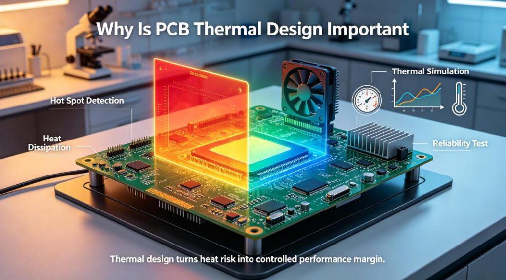
What Is PCB Thermal Design?
PCB thermal design, also known as PCB thermal management, refers to the process of controlling heat generated by electronic components through proper component placement, copper thickness, via design, material selection, stack-up design, and mechanical heat dissipation methods. The goal is to keep the PCB and key components within a safe operating temperature range.
Common heat sources on a PCB include:
- Power MOSFETs
- DC-DC converters
- Linear regulators
- Rectifier diodes
- Relays
- Motor driver ICs
- Compressor control circuits
- Defrost heater control circuits
- LED display or backlight circuits
- High-current connectors
- Power resistors
- Wireless communication modules
The core purpose of PCB thermal design is not simply to make the board cooler. It is to answer several practical engineering questions:
- Where is the heat generated?
- How will the heat be transferred away?
- Are high-power components concentrated in one area?
- Is the copper area large enough?
- Are high-current traces too narrow?
- Are thermal vias required?
- Is thicker copper or high Tg material needed?
- Does the PCB installation area have enough airflow?
- Will heat accumulate inside an enclosed housing?
- Will components age faster during long-term operation?
From an engineering perspective, component temperature rise can be understood with a simple relationship:
Tj=Ta+P×Rθ
Where:
- Tj is the junction temperature
- Ta is the ambient temperature
- P is the power dissipation
- Rθ is the thermal resistance
This means that when power dissipation increases, or when the thermal path is poor and thermal resistance is high, the component temperature will rise. If the temperature remains above the safe operating range for a long time, component life will decrease and failure risk will increase.
Why Is PCB Thermal Design Important?
1. PCB Thermal Design Directly Affects Product Reliability
Heat is one of the major causes of electronic product failure. Many PCBs can work normally during short-term laboratory testing, but temperature problems may appear in real-world conditions, especially under long-term power-on operation, enclosed housings, high load, or changing ambient temperatures.
Excessive temperature may cause:
- Shortened component lifespan
- Capacitance degradation
- Increased MOSFET losses
- Solder joint fatigue or cracking
- PCB material aging
- Increased connector contact resistance
- Electrical parameter drift
- Intermittent product failure
- Reduced system reliability
For B2B customers, thermal issues are not only technical problems. They are also after-sales cost problems. If overheating causes field failures, it may lead to repair costs, product returns, customer complaints, project delays, and loss of brand trust.
Therefore, the earlier PCB thermal design is considered, the lower the risk of redesign and production failure.
2. PCB Thermal Design Affects Component Lifespan
Many components have specified operating temperatures, maximum junction temperatures, and power derating curves in their datasheets. However, the actual PCB operating environment is often more complex than laboratory test conditions.
For example, a power management IC may work normally in open-air testing. But if it is installed inside a closed plastic enclosure, near relays, transformers, MOSFETs, inductors, or power resistors, the actual operating temperature may be much higher.
The following components are especially sensitive to temperature:
| Component Type | Possible Problems Caused by High Temperature |
|---|---|
| Electrolytic capacitors | Shorter life, reduced capacitance, increased leakage current |
| MOSFETs | Higher conduction loss and increased thermal failure risk |
| Voltage regulators | Unstable output or thermal shutdown |
| Relays | Contact aging and excessive coil temperature rise |
| LEDs | Faster lumen degradation and color shift |
| Connectors | Higher contact resistance and local heating |
| Solder joints | Fatigue cracking after thermal cycling |
| Temperature sensors | Reduced measurement accuracy |
PCB thermal design is not only about protecting the PCB itself. It also protects critical components and helps the entire product operate reliably over time.
3. PCB Thermal Design Affects Electrical Performance and Power Efficiency
In high-current PCBs, thermal performance and electrical performance are closely connected.
If copper width is insufficient, copper thickness is too thin, or the current path is poorly designed, the PCB may experience voltage drop and local heating. When the local temperature rises, copper resistance increases further, causing more power loss and forming a negative cycle.
For power boards, motor control boards, compressor driver boards, charging modules, and industrial control PCBs, good thermal design can help:
- Reduce trace losses
- Improve current carrying capacity
- Reduce local hot spots
- Improve power conversion efficiency
- Improve long-term circuit stability
- Reduce the risk of abnormal shutdown
This is why many power PCB projects use 2oz, 3oz, or even thicker copper instead of standard 1oz copper.
4. PCB Thermal Design Helps Reduce Board Warpage and Delamination
A PCB is a composite structure made of copper foil, resin, and fiberglass. These materials do not have exactly the same coefficient of thermal expansion. When local temperature is too high, or when the product experiences long-term thermal cycling, thermal stress may occur inside the PCB.
Thermal stress may cause:
- PCB warpage
- Material delamination
- Plated through-hole cracking
- Solder mask blistering
- Solder joint fatigue
- Reduced reliability of BGA or QFN solder joints
- Mechanical stress on connectors or large component pads
This is especially important in smart home appliances, automotive electronics, industrial equipment, and LED lighting products because these products often operate for long periods and face temperature, humidity, or load changes.
5. PCB Thermal Design Is Related to Product Safety
For power products, smart appliances, charging devices, and industrial controllers, PCB thermal design is also related to safety.
If certain PCB areas remain at high temperature for a long time, it may lead to:
- Reduced insulation performance
- Plastic housing deformation
- Connector burning or discoloration
- Solder joint reliability problems
- Local carbonization
- Failure of protection components
- Potential safety risks in severe cases
Therefore, in products involving high voltage, high current, or continuous power supply, PCB thermal design must be considered together with electrical safety design, including creepage distance, clearance, flame-retardant rating, copper thickness, current path, over-current protection, surge protection, and temperature protection.
Smart Refrigerator PCB Design Example: Why Heat Dissipation Is Required
A smart refrigerator is a typical long-running device in smart homes. Compared with low-power devices such as smart door locks, remote controls, or sensors, a smart refrigerator PCB faces very different challenges.
A refrigerator needs to operate continuously, usually 24 hours a day and 7 days a week. It must control the cooling system and manage the compressor, fans, defrost system, temperature sensors, display panel, communication module, and power supply system. Therefore, a smart refrigerator PCB is not just a simple control board. It is a control platform that integrates power control, load driving, signal acquisition, user interface, and smart communication.
For this type of product, heat dissipation is not optional. It is a basic design requirement.
1. Main Functions of a Smart Refrigerator PCB
A typical smart refrigerator PCB may include the following functions:
| Function Module | Main Function | PCB Design Requirement |
|---|---|---|
| Main MCU | Controls temperature logic, operating modes, alarms, and system coordination | Stable power supply, anti-interference design, reliable reset, long-term stability |
| Compressor control | Controls compressor start, stop, or variable-speed operation | High-current path, reliable drive, surge protection, thermal design |
| Fan control | Controls refrigerator compartment, freezer, or condenser fans | Stable motor drive, low noise, reliable connectors |
| Defrost heater control | Controls heater operation to prevent frost buildup | High-current design, safety isolation, relay or power device reliability |
| Temperature detection | Collects temperature data from refrigerator, freezer, and evaporator areas | Accurate sensor signal, anti-interference design, stable connection |
| Door status detection | Detects door open or close status and triggers alarms or lighting | Stable signal, ESD protection, reliable interface |
| Display and touch control | Supports display, buttons, touch control, and indicators | ESD protection, backlight control, low-noise design |
| Wireless communication | Supports Wi-Fi, BLE, or smart home connectivity | Antenna layout, RF performance, EMI compatibility |
| Power module | Supplies power to control, sensing, communication, and drive circuits | High efficiency, low ripple, safety isolation, thermal derating |
Among these modules, compressor control, fan control, defrost heater control, and power supply circuits are usually the main heat sources.
2. Why 24/7 Operation Makes Refrigerator PCB Design More Difficult
Many electronic products only operate when users turn them on. A refrigerator, however, is almost always working. Even when the compressor is not running continuously, the control board, power module, sensors, and communication module are usually powered for long periods.
This means:
- The power module generates heat for a long time
- Relays, MOSFETs, and driver components experience repeated switching stress
- Capacitors remain in a warm environment for long periods
- Connectors experience current and temperature changes
- The PCB material experiences thermal cycling
- Humidity and condensation risks may exist
- Compressor startup may generate surge current and electromagnetic interference
If thermal design is insufficient, the problem may not appear during the first power-on test. Instead, it may gradually appear after months or years of operation, such as premature capacitor aging, relay contact problems, solder joint fatigue, connector heating, MCU reset issues, or temperature detection drift.
For a refrigerator, PCB design should focus on long-term reliable operation, not only short-term functional testing.
3. Typical Heat Sources on a Smart Refrigerator PCB
The main heat sources on a smart refrigerator PCB usually include:
| Heat Source Area | Possible Cause | Design Risk |
|---|---|---|
| AC-DC power area | Rectifier, transformer, and switching power IC heat generation | Unstable power supply, component aging, local hot spots |
| Compressor drive area | MOSFET, IGBT, driver IC, or relay heating | Excessive temperature rise, switching failure, increased EMI |
| Defrost heater control area | High current through relay or power devices | Contact aging, copper heating, solder joint risk |
| Fan drive area | Motor driver IC or transistor heating | Fan abnormality or unstable control |
| Voltage regulation area | LDO or DC-DC converter heating | MCU power fluctuation or communication failure |
| Display backlight area | LED or backlight driver heating | Brightness degradation or local temperature rise |
| High-current connector | Contact resistance or high terminal current | Local heating, terminal aging, burning risk |
If these heat sources are too concentrated, or if the PCB does not have enough copper area and thermal paths, local hot spots may appear. For a smart refrigerator that operates 24/7, local hot spots may affect not only short-term performance but also power stability, component lifespan, and overall product reliability.
Therefore, during the design and manufacturing stage of a smart refrigerator PCB, engineers should pay attention to copper thickness, material heat resistance, soldering reliability, surface finish, moisture protection, and production testing. For long-running smart appliances, the PCB is not only a circuit carrier. It is also a key factor that affects product reliability.
4. Smart Refrigerator PCB Material and Process Selection
For ordinary control boards, standard FR-4 may be sufficient. However, if a smart refrigerator PCB includes high-power areas, long-term operation, higher temperature rise, or humid environments, material and process selection should be evaluated more carefully.
| Design Item | Recommended Direction |
|---|---|
| PCB material | Standard FR-4 or high Tg FR-4, depending on temperature requirements |
| Copper thickness | 1oz for signal areas; 2oz or higher for power areas if needed |
| Surface finish | HASL, ENIG, or other finishes depending on soldering and reliability requirements |
| Solder mask | Focus on heat resistance, adhesion, and insulation reliability |
| Plated through holes | Ensure reliability in high-current and thermal via areas |
| Conformal coating | Recommended for humidity or condensation-sensitive environments |
| Testing | Electrical testing, visual inspection, functional testing, and temperature rise validation |
For high-reliability smart appliance PCBs, material selection should not be based only on the lowest cost. It should be evaluated based on product life, operating temperature, load conditions, certification requirements, and after-sales risk.
If the PCB remains in a high-temperature environment for a long time, standard materials may age faster. If copper thickness is insufficient, high-current areas may overheat. If plated through-hole reliability is poor, thermal cycling may cause barrel cracking. If moisture protection is not considered, humidity or condensation may reduce insulation performance.
Therefore, material and process selection is not only a cost issue. It is the foundation of long-term smart refrigerator PCB reliability.
5. Key Testing Points for Smart Refrigerator PCBs
A refrigerator PCB should not enter mass production after only a short power-on test. Since a refrigerator is a long-running product, testing should simulate real operating conditions as much as possible.
Recommended testing includes:
Continuous operation temperature rise test
Test the temperature of the power module, compressor drive area, relays, connectors, capacitors, and MOSFETs under conditions close to real product operation.
Compressor startup test
Verify startup current impact, power stability, and whether the MCU is affected by interference.
Defrost cycle test
Check high-current paths and relay temperature rise in the heater control area.
High and low temperature cycling test
Verify PCB, solder joint, and connector reliability under temperature changes.
Damp heat test
Check insulation performance, leakage risk, connector corrosion, and coating protection.
EMI and anti-interference test
Verify that the compressor, motor, and switching power supply do not affect the MCU, sensors, or wireless module.
Aging test
Verify long-term stability of the PCB and critical components through extended operation.
These tests help customers identify problems before mass production and reduce the risk of batch failures. For long-running products such as smart refrigerators, testing should not only answer whether the board can power on. It should answer whether the board can operate reliably for a long time.
Common PCB Thermal Design Methods
In addition to the smart refrigerator example, the following methods are widely used in many high-reliability electronic products.
1. Increase Copper Area
Copper has much better thermal conductivity than standard PCB substrate materials, so increasing copper area is one of the most common thermal design methods.
Common approaches include:
- Increasing copper area around power component pads
- Adding copper pours
- Using internal or bottom copper layers to spread heat
- Avoiding unnecessary copper cutouts around heat sources
- Keeping the thermal path continuous
However, more copper is not always better. Designers also need to consider soldering process, electrical isolation, EMI, and layout space.
2. Use Thermal Vias
Thermal vias transfer heat from the top layer to internal or bottom copper layers. They are commonly used under MOSFETs, power ICs, LEDs, and voltage regulators.
Thermal via design should consider:
- Via quantity
- Via diameter
- Via spacing
- Whether vias need plugging or filling
- Impact on soldering quality
- Connection to bottom-side copper area
For high-power-density PCBs, thermal vias can significantly reduce local hot spots.
3. Select Proper Copper Thickness
Copper thickness directly affects PCB current carrying capacity and heat dissipation. Standard control boards often use 1oz copper, but high-current, high-power, or long-running products may require 2oz, 3oz, or thicker copper.
Thick copper PCBs are commonly used in:
- Power modules
- Motor control boards
- Industrial control boards
- Automotive electronics
- LED lighting
- Charging devices
- Home appliance control boards
- Energy storage equipment
When selecting copper thickness, engineers should consider current level, allowed temperature rise, trace width, board thickness, manufacturing capability, and cost.
4. Optimize Component Placement
Good component placement is the foundation of PCB thermal design.
Designers should avoid placing multiple high-heat components in one small area. For example, MOSFETs, rectifier bridges, inductors, transformers, power resistors, and electrolytic capacitors should not be too crowded.
Recommended layout practices include:
- Keeping reasonable spacing between heat sources
- Keeping heat-sensitive components away from hot areas
- Placing electrolytic capacitors away from high-temperature components
- Placing power devices close to loads or connectors to shorten current paths
- Leaving space for airflow
- Making thermal paths as direct as possible
- Avoiding heat concentration near board edges or enclosed corners
Good layout can improve PCB reliability without significantly increasing cost.
5. Choose Suitable PCB Materials
Different PCB materials have different heat resistance, thermal conductivity, mechanical stability, and cost.
| PCB Material | Features | Common Applications |
|---|---|---|
| FR-4 | Cost-effective and widely used | Standard control boards and consumer electronics |
| High Tg FR-4 | Better heat resistance | Industrial control, automotive electronics, appliance control boards |
| Aluminum substrate | Good thermal conductivity | LED lighting and some power modules |
| Copper substrate | Higher thermal conductivity | High-power modules and special thermal applications |
| Ceramic substrate | High thermal conductivity and high insulation | High-power, high-frequency, and high-reliability applications |
For long-running, high-temperature, or high-power products, selecting the right PCB material can reduce thermal failure risk.
6. Control Temperature Rise in High-Current Traces
High-current traces can easily become hot spots if they are not designed properly.
Designers should check:
- Whether the trace width is sufficient
- Whether copper thickness meets current requirements
- Whether there are narrow bottleneck traces
- Whether enough vias are used for current sharing
- Whether the current path is too long
- Whether connector pads are reinforced
- Whether multi-layer parallel current paths are needed
- Whether additional copper pours or copper bars are needed
For high-current PCBs, it is not enough to check whether the schematic is correct. Engineers must also verify whether the actual copper can carry the required current continuously.
7. Combine PCB Design with Mechanical Heat Dissipation
PCB thermal design is not limited to the PCB itself. It often needs to work together with product mechanical design.
Common mechanical heat dissipation methods include:
- Heat sinks
- Thermal pads
- Metal housings
- Fans
- Ventilation holes
- Metal brackets
- Thermal silicone
- Housing-assisted heat dissipation
If the PCB is installed inside an enclosed housing, copper area alone may not solve all temperature rise problems. In this case, the thermal path should be designed together with the product structure.
Which Products Need PCB Thermal Design the Most?
The following products usually require special attention to PCB thermal design:
| Application | Why Thermal Design Is Important |
|---|---|
| Smart home appliances | Long operating time, power supply, relays, motors, and heater control |
| Power modules | High power density and heat from switching devices and magnetic components |
| Industrial control | Long operating time, complex ambient temperature, high reliability requirements |
| Automotive electronics | Wide temperature range, vibration, and high reliability requirements |
| LED lighting | LED performance and lifespan are highly temperature-sensitive |
| Motor control boards | High-current drive circuits generate significant heat |
| Charging devices | High current and high power increase temperature and safety risks |
| Energy storage equipment | High power, long operation, and safety-critical design |
| Smart refrigerator PCBs | 24/7 operation involving compressor, power supply, fan, and defrost control |
If your product belongs to one of these categories, PCB thermal design should be evaluated before prototyping, not after system testing fails.
How Can a PCB Manufacturer Support Thermal Design?
Many customers think thermal design is only the responsibility of the electronic design engineer, while the PCB manufacturer only needs to produce the board according to Gerber files. This may be acceptable for simple projects. However, for high-power, high-reliability, or mass-production projects, PCB manufacturing experience is very valuable.
A professional PCB manufacturer can provide support in the following areas:
1. Material Recommendation
Based on the product application, operating temperature, power level, and reliability requirements, the PCB supplier can recommend standard FR-4, high Tg FR-4, thick copper PCB, aluminum substrate, or other special materials.
2. Copper Thickness and Trace Width Review
The manufacturer can review whether copper thickness, trace width, copper area, and current paths are suitable for the required current and temperature rise.
3. Thermal Via Process Advice
Depending on soldering and assembly requirements, the supplier can suggest whether thermal vias should be tented, plugged, resin-filled, or plated filled to avoid soldering problems.
4. DFM Check
Design for manufacturability checks can identify risks related to trace width and spacing, copper balance, solder mask bridge, hole-to-copper clearance, board thickness, warpage, panelization, and process capability.
5. Prototype-to-Mass-Production Consistency
A qualified PCB supplier can help customers maintain consistency from prototype to mass production, reducing thermal performance variation, soldering issues, and reliability risks.
For B2B customers, choosing a PCB supplier should not be based only on unit price. It is also important to evaluate whether the supplier can identify manufacturing and reliability risks early.
Common PCB Thermal Design Mistakes
In real projects, the following mistakes are common:
- Only checking the schematic and ignoring the thermal path
- Only checking component specifications and ignoring PCB heat dissipation conditions
- Placing high-heat components too close together
- Using high-current traces that are too narrow
- Using insufficient copper area
- Using too few or poorly positioned thermal vias
- Ignoring the effect of an enclosed housing
- Placing electrolytic capacitors near high-temperature components
- Placing temperature sensors near heat sources
- Skipping continuous operation temperature rise testing
- Moving to mass production after only short prototype testing
- Changing material or copper thickness without re-evaluating process risk
These problems may not be obvious during prototype testing, but they can become serious during mass production or real-world operation.
FAQ: PCB Thermal Design
Q1: Why is PCB thermal design important?
PCB thermal design is important because it directly affects electronic product reliability, component lifespan, safety, power efficiency, and mass production stability. Poor thermal design may cause local overheating, solder joint fatigue, material aging, component failure, or safety risks.
Q2: Why does a smart refrigerator PCB need special thermal design?
A smart refrigerator needs to operate 24/7. Its PCB controls the compressor, fan, defrost heater, power module, sensors, display, and communication module. Long-term operation increases the risk of heat accumulation, component aging, power instability, and local hot spots.
Q3: If the inside of a refrigerator is cold, why does the PCB still get hot?
The PCB control board is usually not located inside the cold compartment. It is often installed near the compressor, rear housing, power module, or enclosed control box. These areas may have higher temperature, limited airflow, and heat generated by power and motor control circuits.
Q4: What are the main ways to improve PCB heat dissipation?
Common methods include increasing copper area, using thermal vias, selecting proper copper thickness, optimizing component placement, choosing suitable PCB materials, improving high-current paths, and combining the PCB with mechanical heat dissipation.
Q5: Can thicker copper solve all PCB overheating problems?
No. Thicker copper can improve current capacity and heat spreading, but it cannot solve all thermal problems. If component placement, thermal paths, vias, enclosure design, or airflow are poor, overheating may still occur.
Q6: Are more thermal vias always better?
Not always. Thermal vias can improve heat transfer, but their number, size, spacing, and process method must be designed properly. Too many or poorly placed vias may cause soldering problems, such as solder wicking or voiding.
Q7: When should PCB thermal design be considered?
PCB thermal design should be considered before PCB layout begins. Early planning of heat sources, current paths, copper thickness, materials, and mechanical thermal paths can reduce redesign cost and shorten project development time.
Conclusion
PCB thermal design is not an optional optimization. It is a key factor that affects product reliability, lifespan, safety, and mass production stability.
For smart refrigerators that need to operate 24 hours a day, 7 days a week, PCB heat dissipation is a necessary requirement. The control board must manage the compressor, fan, defrost heater, power module, sensors, display, and wireless communication system for many years. If thermal design is insufficient, the board may pass short-term testing but fail during long-term operation due to component aging, local overheating, solder joint fatigue, power instability, communication problems, or safety risks.
Therefore, in smart appliances, power electronics, industrial control, motor drives, and long-running equipment, PCB thermal design should be considered from the early stage of the project. By using proper component placement, copper thickness, thermal vias, material selection, EMI control, and temperature rise testing, product reliability can be significantly improved.
If your project involves smart refrigerator PCBs, smart home appliance control boards, power PCBs, or high-current PCBs, it is recommended to work with an experienced PCB manufacturer before prototyping. A professional PCB supplier can help review material selection, copper thickness, manufacturability, and thermal reliability to support smoother mass production.
Need Reliable PCB Manufacturing for Smart Home Appliances?
If you are developing a smart refrigerator PCB, smart appliance control board, power PCB, or high-current PCB, our engineering team can support PCB prototyping, material selection, DFM review, and mass production.
Contact us today to discuss your PCB project and get a manufacturing solution for reliable long-term operation.



0 Comments