




High volume PCB assembly is not simply a prototype order with a larger quantity. It is a controlled production system in which the design, bill of materials, process settings, test program, traceability data, packaging, and release schedule must stay aligned across every build. The safest time to scale is when those controls are documented and a pilot build has shown that they work together.
For buyers, the practical question is not “How many boards count as high volume?” It is “What evidence shows this product can be repeated at the required rate without multiplying defects, shortages, or undocumented changes?” This guide answers that question and provides four working tools: a production-readiness gate, a test-coverage matrix, an RFQ file checklist, and a supplier evidence scorecard.

What High Volume PCB Assembly Actually Changes
There is no universal quantity at which every PCBA project becomes “high volume.” A simple board built on a dedicated line may reach an efficient production mode at a very different quantity from a dense, mixed-technology assembly with long test time and controlled components. Order quantity matters, but board complexity, setup cost, fixture economics, demand cadence, and line allocation determine how the factory must run the job.
The more useful definition is operational: high volume PCB assembly begins when repeatability and production control matter more than build flexibility. A change that was manageable on ten prototypes can create thousands of suspect assemblies after a ramp. This shifts the engineering priorities.
| Prototype or small-batch priority | High-volume priority | Why the shift matters |
|---|---|---|
| Fast design changes | Revision and deviation control | The factory must know exactly which approved configuration to build. |
| Manual troubleshooting | Designed inspection and test coverage | Manual diagnosis is too slow and inconsistent for a production line. |
| Parts that are available today | Approved sources, lifecycle, lead time, and substitution control | A single constrained or changed component can interrupt every release. |
| One successful board | A stable process window and repeatable first-pass results | Functional success does not prove that the assembly process is stable. |
| One delivery date | Forecast, release cadence, line capacity, and recovery planning | Annual demand and shipment pattern affect material and capacity decisions. |
This is why an experienced buyer does not start by asking only for a unit price. The first request should establish whether the product, files, supply chain, and test system are ready for a controlled production ramp.
Use a Production-Readiness Gate Before You Scale
A production-readiness gate is a documented decision to release, limit, or stop the ramp. It prevents commercial pressure from turning open engineering questions into a large batch of nonconforming material. Every gate needs objective evidence, an owner, and a clear stop condition.
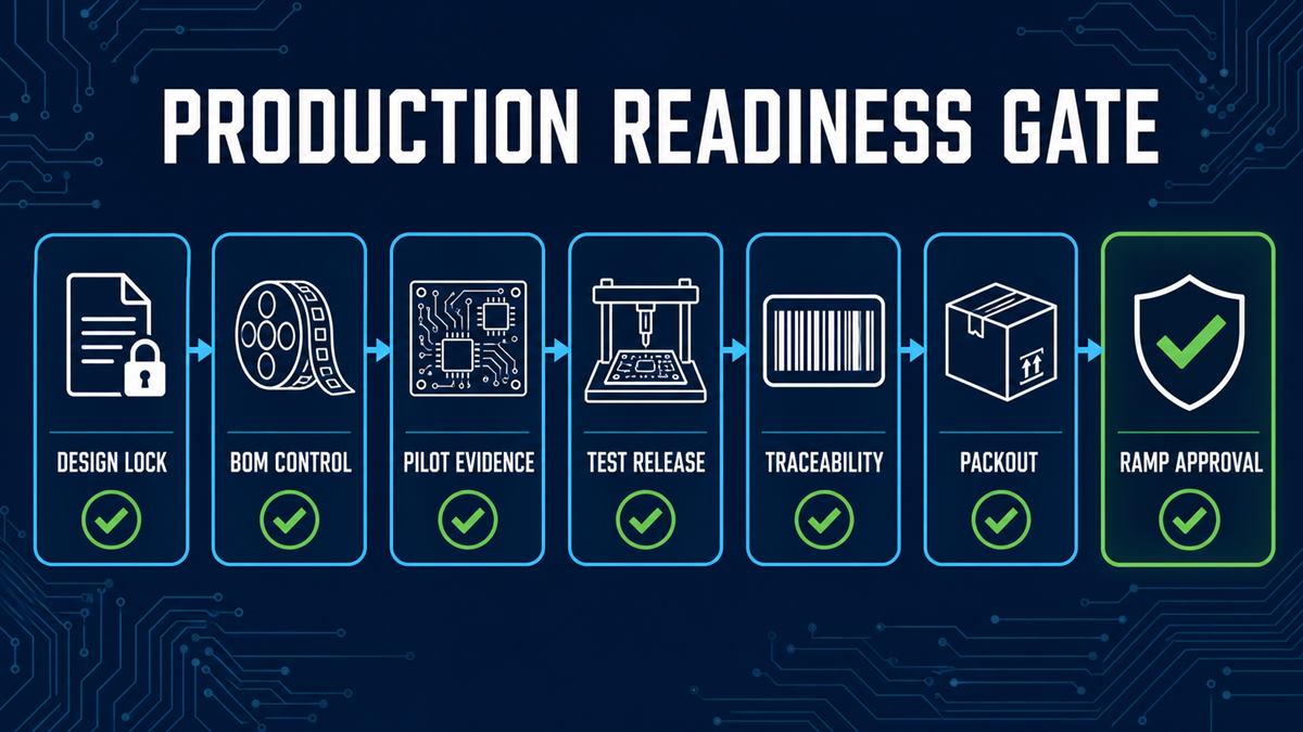
| Gate | Minimum evidence | Stop or limit the ramp when |
|---|---|---|
| Design and DFM | Released fabrication and assembly data; resolved DFM/DFA actions; approved panel and tooling approach | Critical dimensions, polarity, land patterns, panel rails, fiducials, or access remain unresolved |
| BOM and supply | Manufacturer part numbers, approved sources, lifecycle review, alternates policy, and shortage plan | A critical part is unapproved, obsolete, allocation-only, or subject to silent substitution |
| Pilot evidence | First-article results, defect log, corrective actions, rework record, and repeatable process settings | Open defects can affect function, reliability, compliance, or line repeatability |
| Test and firmware | Released test specification, limits, known-good references, program revision, firmware image, and checksum | Coverage gaps or version ambiguity can allow incorrect units to pass |
| Process control | Control plan for incoming material, paste, placement, reflow, inspection, rework, and final release | Critical process limits or reactions to out-of-control conditions are undefined |
| Traceability | Agreed serial/lot structure and links to material, process, program, inspection, test, and shipment records | A failed unit cannot be narrowed to an actionable suspect population |
| Packaging and labeling | Approved label content, pack-out, ESD/moisture protection, quantity per pack, and shipping requirements | Handling or identification can damage assemblies or mix revisions |
| Demand and release plan | Annual forecast, firm release quantity, shipment cadence, buffer policy, and material liability agreement | The quote assumes a batch or schedule that the buyer does not intend to release |
If the design still needs work, complete a documented DFM and DFA review before committing material or production capacity. A waived concern is not the same as a resolved concern; the deviation should state the risk, affected quantity, owner, and expiration.
Move From Prototype to Pilot, Then Release the Ramp
A prototype proves that a design can work. A pilot build asks whether the design can be manufactured, inspected, tested, identified, and packed repeatedly. Treating the pilot as a small sales order misses its purpose: it is a controlled experiment that should expose production risks before the release quantity becomes expensive.
| Stage | Main question | Required output before moving on |
|---|---|---|
| Prototype | Does the electrical, firmware, mechanical, and thermal design work? | Verified functions, documented defects, and a controlled next revision |
| Pilot build | Can the intended factory process build and test the product repeatedly? | First-article approval, process observations, test time, yield data, and closed critical actions |
| Pre-production release | Are files, materials, programs, fixtures, acceptance criteria, labels, and packaging synchronized? | Released build package, approved golden sample, control plan, and signed release decision |
| Ramp | Can output increase without losing control of defects or records? | Defined review intervals, reaction limits, lot release evidence, and capacity status |
| Repeat production | Does each new lot match the approved product and process? | Trend review, approved changes, retained test/trace data, and corrective-action closure |
The pilot quantity should be large enough to exercise the real production route, including both board sides, through-hole or selective-solder operations, programming, test fixtures, coating, depaneling, and pack-out where applicable. The correct number is project-specific. Choose it to reveal process and test variation, not to meet a generic internet threshold.
If your current work is still exploratory, the low-volume PCB assembly process is the better place to validate design changes before freezing the production package.
Lock the Build Identity: Design, BOM, Firmware and Golden Sample
Every finished PCBA needs an unambiguous build identity. The fabrication files, assembly drawing, BOM, placement data, firmware, test program, fixture, approved deviations, and golden sample must describe the same configuration. If one element changes without the others, traceability may identify a serial number without telling you what was actually built.
A practical build identity should include:
- PCB part number and fabrication revision;
- assembly part number and assembly drawing revision;
- BOM revision with manufacturer part numbers, approved alternates, and DNI/DNP status;
- centroid or component placement list revision, including side, rotation, and reference designator;
- firmware filename, version, checksum, programming method, and verification result;
- test specification, test-program revision, fixture revision, and limit set;
- golden-sample serial number and approval record;
- active deviation or concession number, affected quantity, and expiration;
- label format, serialization rule, and packaging revision.
Approved alternates belong in this identity. A component with the same nominal value is not automatically interchangeable: package geometry, tolerance, voltage rating, temperature behavior, startup timing, firmware interaction, regulatory status, or end-of-life risk may differ. Require written approval before a substitution enters production, and decide whether it triggers a limited build, new first article, regression test, or customer notification.
Specify Workmanship and Acceptance Criteria in the Purchase Documents
Industry standards provide a common language, but a purchase order must state which document, revision, class, drawings, customer requirements, and exceptions apply. A broad statement such as “IPC compliant” leaves too much room for interpretation and does not define product function or field reliability.
| Document or requirement | What it helps define | What it does not prove by itself |
|---|---|---|
| IPC-A-610J | Post-assembly acceptability criteria for electronic assemblies | That the product passed its functional, environmental, safety, or lifetime requirements |
| J-STD-001J | Soldering processes and materials requirements | That a specific circuit performs correctly in its end application |
| IPC-1782 / IPC-1782A | Risk-based manufacturing and supply-chain traceability requirements | Which exact data fields and retention period your product needs unless they are agreed |
| Customer fabrication and assembly documents | Product-specific dimensions, materials, orientation, special processes, markings, and exceptions | Functional performance unless test requirements are included |
| Test specification and acceptance limits | Stimulus, measurements, limits, software, fixture, logging, retest, and failure disposition | Long-term reliability outside the tested conditions |
The customer and manufacturer should agree on the applicable requirements before the build. For regulated or high-reliability products, add the product-specific standards, qualification evidence, record retention, calibration, cleanliness, coating, environmental, or validation requirements that actually apply. Do not assume that choosing a higher workmanship class automatically replaces those engineering decisions.
Control the Assembly Process, Not Just Final Inspection
Final inspection can separate some bad units from good ones, but it cannot recover the cost and schedule already consumed by an unstable process. High-volume control should prevent defects, detect drift early, and define what happens when a measurement moves outside its limit.
A useful control plan connects each process step to four items: the critical input, the measurement or check, the reaction limit, and the retained record. Typical checkpoints include:
- Incoming material: verify part identity, quantity, condition, date or lot information, approved source, and moisture-sensitive handling. Follow the device label and applicable IPC/JEDEC handling requirements rather than applying one generic bake rule.
- Solder paste and stencil: control paste condition, stencil identity, aperture condition, print alignment, cleaning interval, and solder paste inspection criteria where used.
- Placement: lock the machine program, feeder setup, reference data, polarity rules, component verification, and first-off review.
- Reflow or soldering: establish a profile for the actual board and component thermal mass; define when the profile must be revalidated after a change.
- First article: inspect the complete configuration before the lot is released, including options, firmware, labels, test, and workmanship—not just visible placement.
- In-process inspection: monitor repeat defects and trends instead of treating each failure as an isolated board.
- Rework: define authorization, method, inspection, retest, traceability, and maximum allowed cycles for the affected product.
- Lot release: require the agreed inspection, test, deviation, and traceability records before shipment.
The purpose is not paperwork for its own sake. A control record should help answer a real failure question: what changed, when did it change, which units may be affected, and what evidence allows the remaining lot to be released? The related PCBA quality-control methods page provides more background on inspection points across the assembly process.
Choose Inspection and Test Coverage by Defect Risk
No single inspection or test method proves that a PCBA is correct. Select coverage from the defects that matter, the physical access available, the failure consequences, the production rate, and the evidence needed at lot release. Then document what each method can and cannot detect.
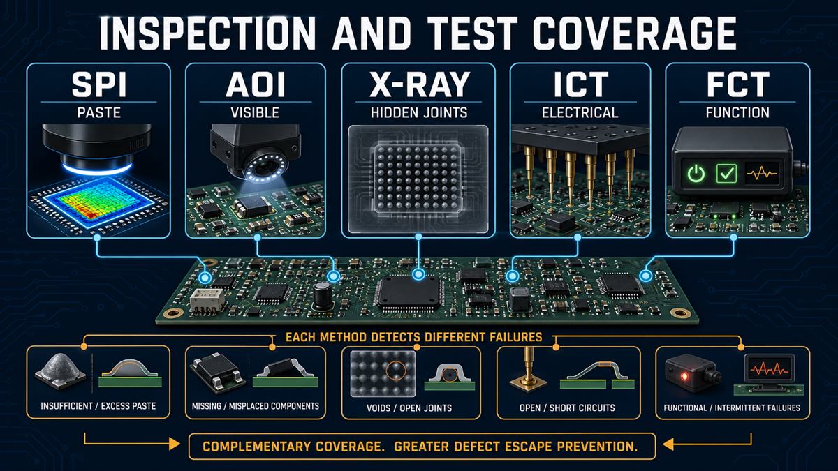
| Method | Strong coverage | Important gap | Evidence to retain |
|---|---|---|---|
| SPI | Paste volume, area, height, alignment, and print trends | Does not prove final joint formation or circuit function | Program revision, thresholds, defect codes, trend or lot summary |
| AOI | Visible presence, polarity, alignment, markings, and solder-joint conditions within the programmed view | Cannot fully inspect hidden joints or prove electrical function | Program revision, defect library, false-call handling, result by serial or lot |
| X-ray | Hidden BGA/QFN joints, bridges, opens, voiding, and internal solder features within equipment capability | Image interpretation and acceptance limits must still be defined | Inspection scope, acceptance criteria, images for failures, disposition |
| ICT | Accessible nets, shorts, opens, selected component values, and some device tests | Requires test access and does not prove all real operating behavior | Program and fixture revision, coverage report, limits, result log, retest history |
| Flying probe | Electrical checks without a dedicated bed-of-nails fixture | Cycle time may be a bottleneck for large releases | Program revision, accessible-net coverage, test time, results |
| Functional test | Defined product behavior under specified power, loads, interfaces, and firmware | A weak test sequence can pass units without exercising critical functions | Test specification, software, fixture, limits, calibration status, serial-level result |
| Programming verification | Firmware identity, write status, checksum, security or configuration steps | Does not prove the rest of the hardware works | Image version, checksum, programmer and script revision, result by serial number |
For high volume, test economics also matter. A dedicated fixture may have meaningful upfront cost but reduce cycle time and improve repeatability. Compare that saving with fixture maintenance, probe access, product life, expected releases, and engineering-change risk. The ICT and functional test comparison can help separate structural electrical checks from end-use functional verification.
Plan Traceability Around the Failures You Need to Isolate
Traceability is useful only when it narrows a failure to an actionable population. A barcode that points to an order number but not to component lots, process programs, test results, or revisions may be adequate for shipping history and inadequate for root-cause analysis.
Start with plausible failure questions. If one field return appears, do you need to identify every PCBA built with the same component lot, solder paste lot, stencil, reflow program, firmware image, test fixture, shift, or approved deviation? The answer determines which links must exist in the record.
A risk-based traceability record may connect the assembly serial or lot number to:
- PCB fabrication lot and bare-board revision;
- critical component manufacturer, part number, date/lot code, and approved source;
- work order, line, machine program, stencil, solder material, and process-profile revision;
- operator or automated station where the customer requires that level of detail;
- AOI, X-ray, ICT, functional-test, and programming result;
- firmware image and checksum;
- rework, deviation, nonconformance, and disposition;
- pack-out, shipment, and customer release.
IPC-1782 frames traceability around perceived risk and agreement between user and supplier. That is the right practical approach: retain enough data to protect the product and supply chain, but define the fields, retention period, access, and response time before production begins.
Model Cost With Yield, Tooling and Test Time
A credible high-volume quote is a model of the actual build, not a generic price per board. Two assemblies with the same dimensions and quantity can have very different cost because of component value, placement count, packages, assembly sides, through-hole work, coating, test time, expected yield, fixtures, programming, packaging, and release schedule.
A useful comparison starts with this structure:
True landed unit cost = bare PCB + components + assembly process + inspection/test + allocated NRE/tooling + expected yield loss/rework + packaging/logistics.
| Cost driver | Question to put in the RFQ | Why it changes the comparison |
|---|---|---|
| Components | Are manufacturer part numbers, approved sources, alternates, excess material, tariffs, and price validity handled the same way? | BOM cost and material liability often dominate the commercial risk. |
| Setup and tooling | Which stencil, programming, fixture, pallet, tooling, and engineering charges are one-time, recurring, or revised after an ECO? | A low unit price may hide NRE or repeat-order conditions. |
| Assembly content | Are both sides, every placement, THT, press-fit, selective solder, cleaning, coating, depaneling, and box-build steps included? | Different scope produces quotes that look comparable but are not. |
| Inspection and test | What percentage is inspected or tested, what fixture/program is included, and how are failures and retests charged? | Test time can become the production bottleneck and a major cost. |
| Yield and rework | Which losses are included, who owns defects caused by design, supplied material, or process, and how is scrap approved? | Quoted price does not show the cost of avoidable escapes or repeated rework. |
| Forecast and releases | Which annual demand, firm batch, shipment cadence, buffer, and cancellation terms does the quote assume? | One 20,000-piece batch and twenty 1,000-piece releases do not consume the same setup and inventory resources. |
Compare total cost at the same scope and acceptance level. If a supplier cannot state its assumptions, the quote is not yet ready for commercial selection, no matter how attractive the headline unit price appears.
Ask for Project Throughput, Not Machine Speed
Placement speed is only one part of production capacity. Your project may be limited by stencil printing, feeder availability, a slow component, bottom-side processing, reflow, selective solder, programming, coating, depaneling, inspection, functional test, or pack-out. A machine’s nominal components-per-hour figure does not equal finished assemblies shipped per hour.
Ask the manufacturer to estimate throughput using your released data and production route:
- What is the expected good-unit output per hour or shift after inspection and test?
- Which operation is the expected bottleneck, and what cycle time was used?
- How many fixtures, pallets, programmers, or test stations are assumed?
- How much line changeover and first-article time is included per release?
- Is the line dedicated, reserved by schedule, or shared with other products?
- What component-kitting, feeder, moisture-handling, or storage limits can interrupt the run?
- How will maintenance, equipment failure, material shortage, or a failed first article affect recovery?
- Which output and yield data will be reviewed during the ramp?
This turns “We have fast SMT machines” into a project-level capacity discussion. It also exposes whether test, material, or changeover—not placement—is controlling the delivery plan.
Build an RFQ Package That Produces Comparable Quotes
A supplier can quote only what the file package defines. Missing information forces assumptions, and different assumptions create different prices, lead times, test scopes, and risk ownership. Use the same controlled package for every supplier you compare.
| RFQ item | Required content | Question it resolves |
|---|---|---|
| PCB fabrication data | Gerber or agreed intelligent data, drill, netlist where applicable, fabrication drawing, stackup, material, finish, copper, dimensions, tolerances, impedance, panel constraints | What bare board must be fabricated and verified? |
| BOM | Reference designators, quantity per board, manufacturer, full MPN, approved alternates, DNI/DNP, lifecycle notes, consigned or turnkey status | Which exact parts may be purchased and fitted? |
| Placement data | X/Y, rotation, side, reference designator, package, origin convention, and matching revision | How will the machine program place each component? |
| Assembly drawing and notes | Polarity, options, special components, hardware, THT/press-fit, solder, cleaning, coating, depaneling, labels, and workmanship requirements | Which build details are not clear from coordinates alone? |
| Programming package | Image, version, checksum, target device, interface, security/configuration steps, verification, and serialization relationship | How is the correct firmware loaded and proven? |
| Test specification | Test method, coverage, fixture, stimulus, loads, limits, software, calibration, data logging, retest, failure codes, and acceptance | What must every tested unit demonstrate? |
| Volume and schedule | Pilot quantity, first production release, annual forecast, release cadence, requested dates, buffer and cancellation assumptions | What material and capacity must be planned? |
| Quality and change control | Applicable standards/revisions/classes, FAI, sampling or 100% requirements, deviation approval, PCN/ECN notification, nonconformance and CAPA expectations | How will the product be accepted and changes controlled? |
| Traceability | Serial/lot format, required material/process/test links, data format, retention period, and retrieval time | How will suspect units be identified and isolated? |
| Packaging and logistics | ESD/moisture protection, labels, quantity per pack, trays or separators, export documents, ship-to location, Incoterms if applicable | What condition and commercial boundary apply at delivery? |
If you need fabrication, sourcing, SMT/THT assembly, and production support under one scope, review the available PCB assembly service before sending the package. Ask the engineering team to list every quote assumption and open technical question; that response is part of the supplier evaluation.
Score Suppliers by Evidence, Change Control and Recovery
Supplier selection should reward evidence, not the number of capability claims on a web page. The weights below are a starting framework; adjust them for your product risk, regulatory environment, supply exposure, and commercial priorities.
| Criterion | Suggested weight | Evidence to request |
|---|---|---|
| Engineering and production readiness | 15% | DFM/DFT findings, pilot plan, first-article format, open-action ownership, release criteria |
| Process control | 15% | Project process flow, control-plan example, critical limits, reaction plan, calibration and maintenance controls |
| Inspection and test coverage | 15% | Coverage matrix, fixture/program approach, cycle time, sample result, failure/retest rules |
| Supply chain and change control | 15% | Approved-source policy, alternates workflow, lifecycle review, shortage escalation, PCN/ECN and deviation process |
| Traceability | 10% | Example record linking serial or lot to material, process, firmware, inspection, test, rework, and shipment |
| Project capacity and recovery | 10% | Actual route-based UPH, bottleneck analysis, line allocation, fixture count, backup and recovery plan |
| Quality system and corrective action | 10% | Current certificates with scope, nonconformance flow, root-cause/CAPA example, audit and record-retention approach |
| Commercial clarity | 10% | Complete assumptions, price validity, NRE, material liability, yield/scrap ownership, logistics and change charges |
Watch for red flags: a very low quote with many “TBD” items; substitutions allowed without written approval; capacity described only by machine speed; test described as “available” without coverage, fixture, software, limits, or records; certificates provided without current scope; and engineering feedback that is not revision-controlled.
The strongest supplier is not always the one with the most machines or the lowest initial price. It is the one that can show how your exact product will be controlled, how a change will be approved, how a failure population will be isolated, and how production will recover without losing configuration integrity.
Frequently Asked Questions
What quantity is considered high volume PCB assembly?
There is no universal threshold. The production mode depends on board complexity, setup and fixture cost, test cycle, automation, release cadence, and annual demand. Define high volume around the controls and capacity your project needs, not a generic piece count.
When is a PCBA ready to move from prototype to high volume?
It is ready when the design and BOM are controlled, critical DFM/DFT issues are closed, a pilot has exercised the intended route, test and firmware are released, supply risk is understood, and traceability and acceptance evidence are agreed. An open critical action should limit or stop the ramp.
Which files are required for a high volume PCB assembly quote?
At minimum, provide PCB fabrication data, fabrication and assembly drawings, BOM with full MPNs, placement data, build notes, quantity and schedule. Add programming, test, workmanship, traceability, labeling, packaging, and logistics requirements when they are in scope.
Is AOI enough for high volume PCB assembly quality control?
No. AOI is strong for programmed visible conditions, but it cannot prove all hidden joints, component values, firmware, electrical behavior, or end-use function. Combine methods according to the defect risks and document the remaining gaps.
When does ICT make sense for a production build?
ICT becomes attractive when sufficient test access exists and repeated releases can justify fixture development and maintenance. Compare fixture cost with coverage, test time, expected product life, volume, change frequency, and the cost of escaped defects.
How should component substitutions be controlled?
Use an approved alternates list and require written authorization before a new MPN enters production. The review should cover form, fit, function, lifecycle, compliance, process compatibility, firmware interaction, and any test or first-article work triggered by the change.
Why can’t a supplier give a reliable unit price from quantity and board size alone?
Those inputs do not define the BOM value, placements, packages, sides, soldering route, tooling, test time, yield risk, coating, programming, packaging, schedule, or material liability. A reliable price needs a controlled RFQ package and explicit assumptions.
What traceability should a high volume PCBA include?
Traceability should match the failures you may need to isolate. Depending on risk, link the assembly serial or lot to PCB and component lots, revisions, process programs, firmware, inspection/test results, rework, deviations, and shipment records.
Should a prototype and high volume build use the same manufacturer?
Using one manufacturer can reduce data transfer and process-change risk, but it is not automatically the best choice. Confirm that the prototype process represents the intended production route and that the supplier can provide the required capacity, test, controls, records, and recovery plan.
How do forecasts and release schedules affect the quote?
They affect component purchasing, price breaks, material liability, storage, line changeovers, fixture utilization, and delivery planning. Give both the annual forecast and the firm release schedule so the supplier does not quote an unrealistic single batch.
Does IPC-A-610 Class 3 prove that the product will be reliable?
No. It defines assembly acceptability criteria at the specified class; it does not replace product-specific functional, environmental, safety, regulatory, or lifetime validation. State all applicable requirements in the purchase and test documents.
What should happen when a pilot build finds a repeat defect?
Contain the affected units, record the defect and suspect population, identify root cause, implement and verify corrective action, and decide whether another limited build is needed. Do not release the full ramp only because defective pilot units were reworked successfully.
Prepare Your High Volume PCB Assembly RFQ for Engineering Review
Start with one controlled package: fabrication data, BOM, placement file, assembly drawing, test and programming requirements, pilot and release quantities, annual forecast, workmanship criteria, traceability, labels, and packaging. State which items are released and which are still open. That makes the first engineering response more useful and the resulting quote easier to compare.
Send the package to [email protected] or contact the pcbtry.com engineering team. Ask for a written list of DFM/DFT questions, quote assumptions, proposed inspection and test coverage, material risks, expected project throughput, and the pilot-to-ramp release plan before approving production.



0 Comments