




What Is FR4 PCB Material?
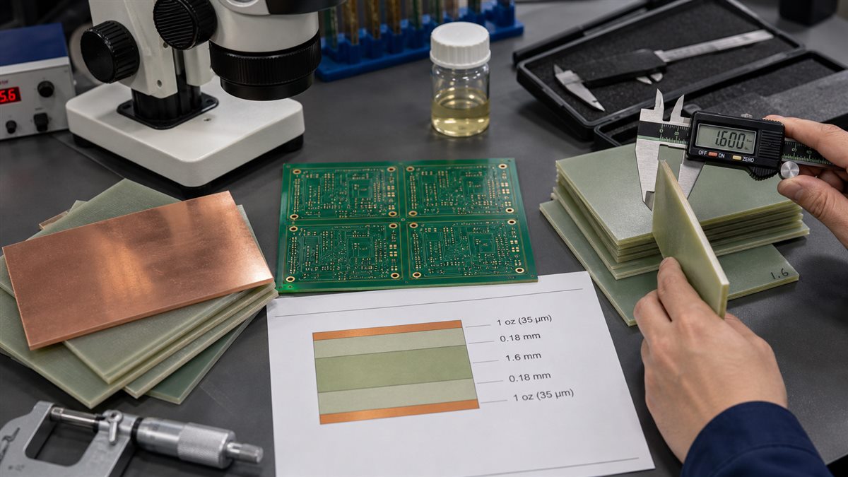
FR4 PCB material is the most common base material used for printed circuit boards. It is a glass fiber reinforced epoxy laminate with copper foil bonded to one or both sides. After fabrication, copper is etched into circuit patterns and the laminate becomes the structure of the PCB.
FR4 is popular because it balances cost, mechanical strength, electrical insulation and manufacturing availability. It works well for many consumer, industrial, control, LED, power and general digital PCB designs.
FR4 is not one exact material. Different FR4 grades can have different Tg, dielectric properties, thickness tolerance, CTI, thermal performance and lead-free compatibility.
Key FR4 PCB Material Properties
| Property | What it means | Why it matters |
|---|---|---|
| Tg | Glass transition temperature | Affects heat resistance and lead-free process margin |
| Dk | Dielectric constant | Affects impedance and signal speed |
| Df | Dissipation factor | Affects high-frequency loss |
| CTI | Tracking resistance indicator | Important for insulation safety in some products |
| Thickness | Finished board thickness | Affects stiffness, impedance, connector fit and drilling |
| Copper weight | Copper thickness on layers | Affects current, heat and trace fabrication |
Standard Tg vs High Tg FR4
Tg is the temperature region where the laminate changes from a glassy state toward a softer state. Standard FR4 can be enough for many boards, but high Tg FR4 may be preferred for lead-free assembly, higher operating temperature, thicker boards, multilayer boards or reliability-sensitive products.
High Tg does not automatically make a board better in every way. It can add cost and should be chosen for a real thermal or reliability reason.
FR4 Thickness Selection
Common finished PCB thickness values include 1.6 mm, but thinner and thicker boards are also used. Thickness affects mechanical strength, connector fit, impedance, weight and drill aspect ratio.
A very thin board may bend during assembly. A very thick board may make small plated holes harder to manufacture reliably. Choose thickness based on mechanical design and fabrication limits, not habit alone.
Copper Weight on FR4 Boards
Copper weight affects current capacity, heat rise, voltage drop and trace fabrication. Standard signal boards often use 1 oz finished copper, while power boards may require heavier copper.
Heavier copper is not always better. It can require larger spacing and may make fine traces harder to etch. If the design has both fine signals and high current, discuss layer-specific copper choices with the manufacturer.
FR4 and Controlled Impedance
FR4 can be used for many controlled impedance boards, but the calculation depends on actual stackup, trace geometry, copper thickness and dielectric properties. Generic FR4 values may not be enough for tight impedance control.
If you need 50 ohm, 90 ohm or 100 ohm impedance, send the target impedance, trace width, spacing, layer and stackup requirement. The manufacturer can confirm a buildable structure.
When FR4 May Not Be Enough
FR4 is not ideal for every board. High-frequency RF, very low-loss digital channels, extreme temperature, high-power thermal designs or special safety requirements may need different materials.
Do not choose a high-performance material only because it sounds premium. The right question is whether FR4 can meet the electrical, thermal, mechanical and reliability requirements with margin.
FR4 Material Selection Guide
| Project condition | FR4 choice to consider | Check before ordering |
|---|---|---|
| General digital board | Standard FR4 | Thickness, copper and finish |
| Lead-free reflow or higher heat | High Tg FR4 | Tg, Td and assembly profile |
| Controlled impedance | FR4 with confirmed stackup | Dk, thickness and trace geometry |
| Power board | FR4 with heavier copper if needed | Current, trace width and temperature rise |
| RF or low-loss board | Maybe non-FR4 material | Loss, frequency and supplier capability |
Common FR4 PCB Material Mistakes
| Mistake | Why it matters | Better approach |
|---|---|---|
| Writing only “FR4” on the drawing | Grade may be unclear | State Tg or material requirement when needed |
| Ignoring thickness tolerance | Connector or enclosure fit may fail | Confirm finished thickness and tolerance |
| Using heavy copper with fine traces | Etching becomes harder | Balance current and trace geometry |
| Assuming FR4 is always good for RF | Loss may be too high | Check frequency and Dk/Df requirements |
What to Send for an FR4 PCB Quote
- Gerber or ODB++ files.
- Layer count and stackup requirement.
- Finished board thickness and tolerance.
- Copper weight for each layer.
- Tg or material grade requirement.
- Controlled impedance table if required.
- Surface finish and solder mask requirements.
- Operating environment or reliability notes.
FAQ
Is FR4 the same for every PCB factory?
No. FR4 is a broad material category. Exact laminate brand, Tg, Dk, Df and availability can vary, so special requirements should be stated.
Is high Tg FR4 always better?
Not always. High Tg improves thermal margin for some designs but can add cost. Use it when heat, reflow or reliability requirements justify it.
Can FR4 be used for impedance control?
Yes, but the stackup and dielectric data must be confirmed. Do not rely only on a generic calculator value.
What is the standard FR4 PCB thickness?
1.6 mm is common, but many other thicknesses are available. The right thickness depends on mechanical and electrical requirements.
Confirm FR4 Material Before PCB Fabrication
FR4 PCB material is a practical default, but the exact Tg, thickness, copper weight and stackup still need review before production.
PCBtry can review your PCB fabrication files, FR4 material requirement, copper weight and impedance needs. Send your Gerber files, stackup notes and material requirements through the contact page before ordering.



0 Comments