




What Is an FR4 Datasheet?
An FR4 datasheet is a supplier document that lists measured or guaranteed properties for a specific laminate grade or material family. It may include Tg, Dk, Df, CTE, Td, CTI, moisture absorption, flammability, peel strength, thickness options and copper-clad construction. For PCB buyers, the datasheet is useful only when the values are connected to the actual board requirement.
The common mistake is to download a datasheet, find one attractive number, and assume the board is solved. A datasheet is not a finished PCB stackup. It does not replace DFM review, impedance calculation, assembly review or supplier capability confirmation.
How to Read an FR4 Datasheet Without Misusing It
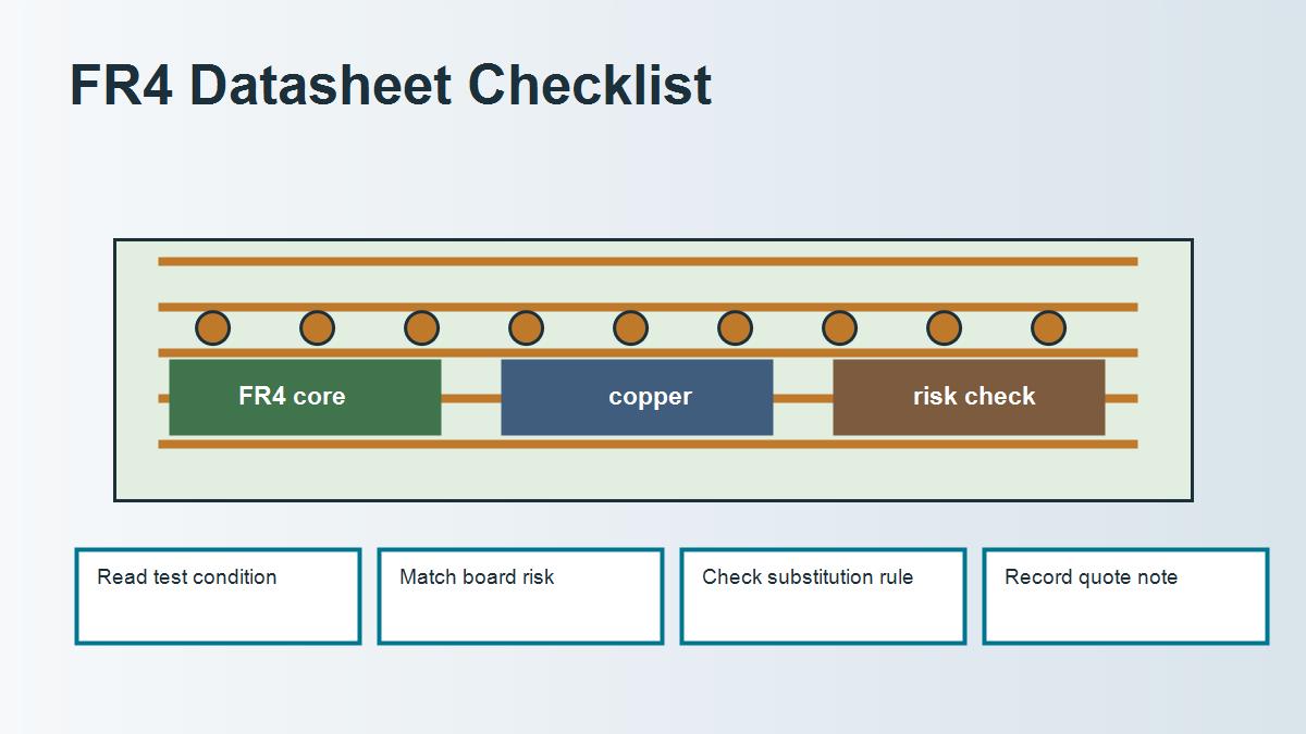
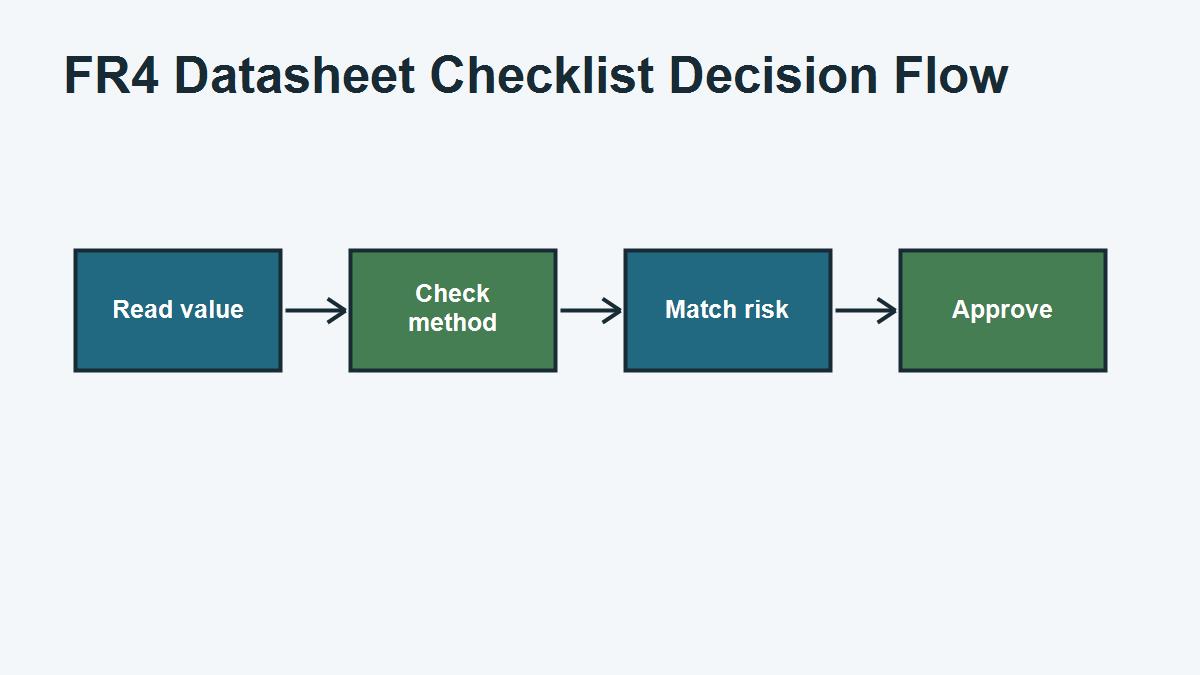
Start by identifying the exact material grade and revision. Then check the test method and condition for each property. Dk and Df may be reported at a specific frequency. Tg may be measured by a stated method. CTE may be separated by axis and temperature range. Thickness values may describe laminate options, not the finished PCB thickness after copper, solder mask and processing.
For quotation, the datasheet should answer a practical question: does this material grade fit the thermal, electrical, mechanical and process risk of the board? If the answer is unclear, ask the PCB supplier what material they normally stock and what equivalent substitutions are allowed.
FR4 Datasheet Fields Buyers Should Check
| Field | What it tells you | Why it matters | Question to ask |
|---|---|---|---|
| Tg | Thermal transition behavior | Assembly and reliability margin | Is high-Tg required for this board? |
| Dk | Dielectric constant | Impedance and propagation | At what frequency and method was it measured? |
| Df | Dielectric loss | High-speed and RF loss | Is standard FR4 loss acceptable? |
| CTE | Thermal expansion | Via and hole reliability | Which axis and temperature range apply? |
| CTI | Tracking resistance indicator | Insulation safety in some applications | Does the end product require a CTI class? |
| Thickness | Available laminate or core thickness | Stackup and enclosure fit | What is the finished board tolerance? |
Datasheet Value vs Finished PCB Reality
A datasheet describes material behavior under controlled tests. A finished PCB adds design geometry and process variation. Copper pattern, press cycle, resin flow, drill plating, solder mask, surface finish and panel processing all affect the final board. Therefore, a datasheet should support the engineering decision, not replace the manufacturing review.
For example, a Dk number can guide material selection, but controlled impedance still needs the final stackup. A Tg number can guide thermal review, but reliability also depends on board thickness, hole size, copper distribution, assembly profile and test requirement. A thickness option can guide construction, but finished board tolerance must be specified separately.
FR4 Datasheet Comparison Table
| Comparison point | Standard FR4 grade | High-Tg FR4 grade | Low-loss grade | Buyer meaning |
|---|---|---|---|---|
| Main reason to choose | General PCB cost and availability | Thermal reliability margin | Signal loss and Dk control | Choose by risk, not by label |
| Key datasheet fields | Thickness, Tg, CTI | Tg, Td, CTE | Dk, Df, frequency data | Review the fields that match the design problem |
| Typical risk if ignored | Wrong tolerance or weak callout | Assembly reliability concern | Loss or impedance mismatch | Ask before production |
Real Procurement Case: A Datasheet Number Caused a Quote Gap
A buyer requested a specific FR4 datasheet grade because one Dk value looked suitable for a controlled-impedance design. The PCB factory did not normally stock that exact grade for quick-turn production and proposed an equivalent material. The buyer first rejected the substitution, but the review showed that the real requirement was impedance control within tolerance, not the brand name itself.
The final solution was to approve a stocked material with documented Dk data, a controlled stackup and an impedance coupon requirement. The quote became faster and more realistic without abandoning the electrical requirement.
Buyer takeaway: use the datasheet to define performance needs, but confirm stocked material, acceptable equivalents and test requirements with the PCB supplier.
FR4 Datasheet Checklist for RFQ
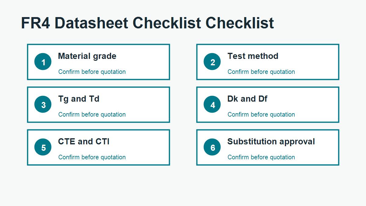
- Exact material grade or acceptable equivalent family.
- Tg requirement and assembly profile.
- Dk/Df frequency range if signal performance matters.
- Finished board thickness and tolerance.
- Copper weight and layer count.
- CTI or insulation requirement if relevant.
- Whether material certificate, test report or impedance report is needed.
- Whether substitutions need written approval.
Ask PCBTRY to Review the Datasheet Requirement
If you have an FR4 datasheet but are not sure how to translate it into a PCB quote, send PCBTRY the datasheet, Gerber files, stackup, assembly conditions and test requirements. PCBTRY can help check which properties matter and whether a stocked equivalent material can meet the design goal.
Common FR4 Mistakes That Cause Quote or Production Problems
The most common FR4 mistake is treating a short material word as a complete production requirement. A PCB supplier cannot reliably quote every risk from the phrase “FR4” alone. The quote also depends on board thickness, layer count, copper weight, surface finish, hole structure, impedance, assembly process, test requirement and delivery quantity. If those details are missing, the first quote may look fast but the order can still change after engineering review.
A second mistake is comparing suppliers only by unit price. One quote may assume standard FR4, loose tolerance and no special report. Another quote may include high-Tg material, impedance coupon, tighter inspection or a controlled stackup. If the assumptions are different, the prices are not truly comparable. Buyers should ask what is included before deciding that one supplier is more expensive.
A third mistake is using a datasheet value without checking how the finished board will be built. Dk, Df, Tg and CTE values are useful, but they must be connected to the actual stackup, copper construction, press process and assembly exposure. For sensitive designs, the better workflow is to share the real files and let the manufacturer confirm a practical build.
Questions to Send With an FR4 PCB RFQ
| Question | Why it helps | What the supplier can confirm |
|---|---|---|
| Is standard FR4 acceptable for this application? | Prevents over-specifying or under-specifying material | Material family, Tg need and substitution rule |
| Can you propose a manufacturable stackup? | Connects material to real production | Core, prepreg, copper and thickness tolerance |
| Does this board need impedance control? | Protects signal integrity requirements | Trace geometry, Dk assumption and coupon options |
| Are there DFM risks in the files? | Finds issues before production | Drill, spacing, annular ring, solder mask and outline risks |
| What should be changed before mass production? | Turns the quote into a decision tool | Cost, yield, testing and reliability improvements |
FR4 FAQ for PCB Buyers
Can I simply write FR4 on the drawing?
You can do that for many simple boards, but it is not enough for every project. If the board has controlled impedance, high assembly temperature, heavy copper, dense vias, RF signals or strict reliability requirements, add the relevant material and stackup notes.
Does higher Tg always mean better FR4?
Higher Tg can improve thermal margin, but it does not automatically solve signal loss, impedance, current carrying or moisture concerns. Match the material upgrade to the actual risk.
Should prototypes and mass production use the same FR4 grade?
For low-risk prototypes, an equivalent stocked FR4 may be acceptable. For controlled or certified products, keep the material rule consistent and document any approved substitution before production.



0 Comments