




How do you find the correct schematic for a PCB?
Photograph the board, record every model, board, assembly, and revision number, then search those exact identifiers in manufacturer support pages, service manuals, regulatory filings, authorized distributors, reference-design libraries, and reputable repair communities. Verify any candidate against connector pinout, component references, IC part numbers, power rails, and revision markings. If no exact schematic exists, reconstruct only the circuit section needed for the repair or engineering task and label it as reverse-engineered.
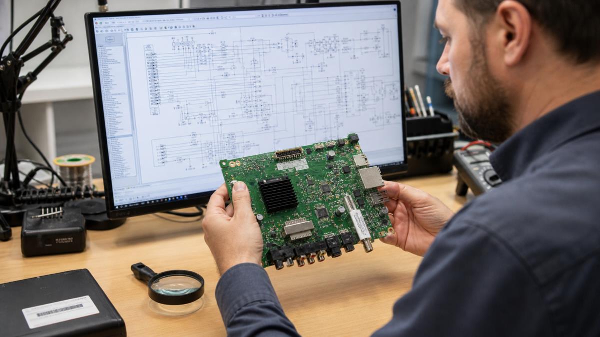
Create a board identity sheet before searching
Disconnect power, follow the product’s service precautions, and photograph both sides of the board at high resolution. Record the product model, serial family, board name, PCB number, assembly number, revision, date code, firmware label, regulatory ID, and manufacturer logos. Note daughterboards and connector labels. Search each identifier exactly, with and without punctuation.
| Identifier | Where it may appear | Why it matters |
|---|---|---|
| Product model | Case, rating label, manual | Finds the product family |
| PCB/board number | Silkscreen, sticker, etched copper | Targets the physical board |
| Assembly number | Barcode or production label | May distinguish populated variants |
| Revision | Near board number or label | Separates changed circuits and pinouts |
| FCC or regulatory ID | Product label | May lead to filings, photos, and reports |
| Major IC markings | Component package | Finds datasheets and reference designs |
Search the original manufacturer first
Look for service manuals, maintenance documents, technical bulletins, parts lists, evaluation-board files, product change notices, and archived support pages. Search the product model together with terms such as service manual, schematic, circuit diagram, board number, and PDF. For industrial equipment, ask the manufacturer’s service department or authorized distributor and provide the serial and board revisions.
Check regulatory filings and official technical libraries
Regulatory databases may contain internal photographs, block diagrams, operational descriptions, test reports, and sometimes schematics. Availability and confidentiality differ by filing, so do not assume every FCC ID contains a full circuit. Semiconductor vendors’ reference designs, evaluation-board user guides, datasheets, and application notes can explain sections built around a known controller, regulator, radio, or interface, but they are reference evidence—not proof that the product copied the circuit unchanged.
Use service-manual and repair communities carefully
Specialist forums and archives can identify alternate board numbers, common failures, voltage maps, boardviews, or service documents. Evaluate who uploaded the file, whether the thread shows the exact revision, and whether multiple users confirm it. Avoid files presented as leaked confidential data, bypass paywalls only through legitimate access, and scan downloads before opening them. Do not run unknown executables merely to view a schematic.
Know the difference between a schematic and a boardview
| Document | Shows | Does not necessarily show |
|---|---|---|
| Schematic | Electrical components, nets, values, and functional connections | Exact physical routing and placement |
| Boardview | Component locations, pads, nets, and physical board references | Circuit intent, values, or complete functional explanation |
| PCB layout source | Placement, copper, layers, vias, rules, and manufacturing geometry | Complete electrical rationale if schematic is absent |
| Service manual | Disassembly, troubleshooting, adjustments, parts, sometimes circuits | Every production revision |
| Block diagram | Major functional relationships | Component-level connections |
Search by the board number, not only the retail brand
One retail model may use several boards, and one board may appear in multiple branded products. Put the exact board number and revision in quotation marks, then try the base number without suffixes. Search image results to compare connector placement and component layout. Also search major controller part numbers with the board number or product function.
Verify a candidate schematic before trusting measurements
Check several independent anchors. Connector reference and pin count should match. Major IC designators, packages, and part numbers should agree. Power-input protection, regulator topology, crystal frequency, memory, and interface circuits should appear in the expected locations. Confirm the schematic revision and page title. One matching chip is not enough.
- Match at least several distinctive components and connectors.
- Confirm ground points with power removed.
- Compare net continuity only where safe and accessible.
- Mark every mismatch instead of silently adapting the document.
- Do not apply a published voltage until the rail identity and reference are confirmed.
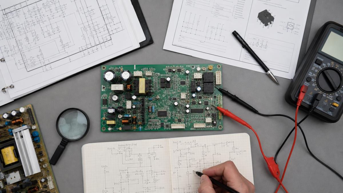
Build a functional map when no exact schematic exists
Divide the board into power input, conversion, processing, memory, analog, communications, drivers, loads, and connectors. Identify major parts from their top markings and obtain official datasheets. Datasheet pin functions help establish likely rails and interfaces. Photograph the work and annotate a copy rather than writing directly on the only board.
Trace an unpowered circuit systematically
Remove all energy sources and discharge stored energy using the service procedure. Use continuity or resistance measurements suitable for the circuit and instrument. Start from a known connector pin or device pin, follow visible copper, vias, zero-ohm links, inductors, protection parts, and test points, and give each confirmed net a temporary name. Record measurement points and meter polarity. In-circuit components create parallel paths, so a beep is evidence of low resistance, not always a direct copper connection.
Reconstruct only the section you need
For a dead power rail, reconstruct the input protection, converter, feedback, enable, output, and load branches before mapping unrelated circuits. For a communication fault, focus on connector protection, transceiver, termination, isolation, and controller pins. A bounded verified partial schematic is more useful than a guessed full-board drawing.
Use safe limits for powered investigation
Powered measurements can expose hazardous voltage, stored energy, hot parts, moving equipment, lasers, RF, or mains-referenced circuits. Follow the product’s service documentation and use qualified personnel, isolation, probes, personal protection, and current limiting appropriate to the equipment. If the energy, topology, or measurement reference is unknown, stop and obtain expert support. Never use an oscilloscope ground clip by assumption on an unidentified primary-side circuit.
Record evidence and confidence in the reconstructed schematic
| Confidence | Evidence | How to mark it |
|---|---|---|
| Confirmed | Visible connection plus continuity or authoritative source | Normal net with source note |
| Strongly supported | Datasheet topology and multiple matching observations | Net with verification pending |
| Inferred | Expected connection hidden under package or inner layer | Dashed/flagged connection |
| Unknown | Ambiguous path or inaccessible node | Explicit open question |
Include board revision, date, author, instrument, photos, source URLs, and unresolved mismatches. Never present a reconstructed drawing as the manufacturer’s original schematic.
Compare files before ordering a replacement PCB
A repair sketch is not automatically a manufacturing package. Reproduction also requires footprints, board outline, layer stackup, copper geometry, vias, materials, finishes, controlled impedance, assembly data, and test requirements. If the objective is to remake the board, capture the design in a controlled CAD system and perform electrical, DFM, mechanical, and prototype validation.
Avoid common schematic-search mistakes
- Searching only the retail model and ignoring the board number
- Using a document from a different revision without checking differences
- Assuming an application-note circuit exactly matches the product
- Confusing a boardview, wiring diagram, block diagram, and schematic
- Downloading unknown executable viewers or untrusted archives
- Measuring powered equipment before identifying hazards and references
- Treating continuity through parallel components as a direct net
- Drawing hidden-layer connections as facts without marking inference
PCB schematic FAQ
Why can I not find a schematic by product model?
Consumer products often use multiple board revisions, and manufacturers may not publish component-level service data. Search the board number, assembly number, revision, and major IC markings.
Can an FCC filing contain a PCB schematic?
It may contain diagrams, internal photos, or technical descriptions, but exhibits vary and some material may be confidential. Use the official filing and verify it against the board.
Is a boardview the same as a schematic?
No. A boardview is primarily a physical component and net map; a schematic expresses the electrical circuit and functional relationships.
Can I create a schematic from PCB photographs?
You can reconstruct visible sections, especially on simple boards, but inner layers, hidden pads, parallel paths, and unknown components require measurements and explicit uncertainty.
How do I identify an unmarked component?
Use its package, board reference, surrounding circuit, connected pins, measurements, and comparable designs. Do not assign a part solely from appearance.
What should I search after a board number?
Try the exact number with schematic, service manual, circuit diagram, boardview, PDF, revision, or the device model. Also search without separators and suffixes.
How do I know a downloaded schematic is correct?
Match revision, connectors, reference designators, major ICs, power topology, and several continuity anchors. Record every discrepancy.
Can I measure continuity on a powered board?
No. Continuity and resistance modes are generally used on de-energized circuits after stored energy is safely discharged.
Can a manufacturer recreate a PCB from a schematic alone?
No. Fabrication needs physical layout and manufacturing data; assembly also needs BOM, placement, drawings, and test requirements.
When should I stop reverse engineering?
Stop when hazardous energy, inaccessible layers, unknown references, legal restrictions, or insufficient evidence make the work unsafe or unreliable. Escalate to the manufacturer or a qualified lab.
Request PCB reconstruction or manufacturing review
Send clear board photographs, dimensions, every visible identifier, the device model, known source files, the exact revision, and the purpose of the work through the PCBTRY contact page. State whether you need document matching, a verified partial schematic, layout reconstruction, DFM review, or a manufacturable replacement package.



0 Comments