




First, Fix the Terminology: Mechanical Shock Is Not Electrical Shock
If you search for “vibration vs electric shock PCB,” the comparison probably needs one correction. Vibration testing is normally compared with mechanical shock testing, not electrical shock.
Download the test-plan checklist and worksheet
Download the PCB Vibration and Mechanical Shock Test Plan Checklist and Worksheet (PDF). This is an original, source-bounded planning aid, not a test report or universal specification.
- Document the real operating, transport or handling load.
- Confirm the applicable standard or customer specification and edition.
- Define the representative assembly, enclosure, mounting and cable configuration.
- Specify control, response and live electrical monitoring channels.
- Approve numerical inputs, tolerances and pass/fail criteria before testing.
- Record the required axes and product orientations.
- State whether the assembly is powered, loaded or unpowered.
- Define baseline and post-test inspection evidence.
- Approve test order and intermediate inspection points.
- Obtain design, quality and laboratory approval before exposure.
| Term | What it means | Typical engineering question |
|---|---|---|
| Vibration | Repeated oscillatory motion, often represented as sine vibration or random vibration over a frequency range | Will the PCB assembly survive repeated dynamic loading, resonance and fatigue? |
| Mechanical shock | A short transient load described by a pulse, peak acceleration, duration and direction | Will the assembly survive a drop, impact, handling event or sudden vehicle load? |
| Electrical shock / ESD | Hazardous electrical energy or an electrostatic discharge event | Is the product electrically safe, and can its circuitry withstand an electrical transient? |
This article focuses on PCB vibration vs mechanical shock testing. If the actual concern is personnel protection, insulation, dielectric withstand or ESD immunity, you need an electrical-safety or EMC/ESD test plan instead. Do not use a passed mechanical test as evidence of electrical safety.
PCB Vibration vs Mechanical Shock at a Glance
Vibration and shock can stress the same solder joint, connector or board, but they do so with different time histories. That difference changes the test equipment, control parameters, failure mechanisms and evidence you should collect.
| Comparison point | Vibration testing | Mechanical shock testing |
|---|---|---|
| Load character | Repeated oscillation | Short transient event |
| Common field sources | Engines, fans, pumps, rail vehicles, aircraft, machinery and transport | Drops, impacts, rough handling, sudden stops and discrete vehicle events |
| Typical descriptors | Frequency range, sine amplitude or random PSD, overall RMS, duration and axes | Peak acceleration, pulse duration, pulse shape, velocity change, direction and number of pulses |
| Dominant concern | Resonance, cyclic strain, fatigue and intermittent contact | Peak board deflection, abrupt inertia loads, cracking, separation and momentary interruption |
| Typical equipment | Electrodynamic or hydraulic shaker with a fixture | Shock machine, drop table or other pulse-generating system |
| Essential measurements | Control acceleration, response acceleration, transmissibility and live electrical monitoring where needed | Actual pulse at the fixture, board response, pulse tolerance and live electrical monitoring where needed |
| What a pass proves | Survival of the defined vibration profile and acceptance criteria | Survival of the defined shock pulses and acceptance criteria |
A pass in one column does not automatically cover the other. The correct test is the one that represents a documented transport or operating event, not the one with the largest-looking acceleration number.
What Vibration Testing Reveals on a PCB Assembly
Vibration repeatedly flexes the board and moves component masses. When excitation approaches a structural natural frequency, board response can be much higher than the motion measured at the fixture. That is why a control accelerometer on the fixture and one or more response measurements on the assembly answer different questions.
Sine vibration is useful when the requirement calls for a controlled sweep, a resonance search or a dwell at a defined frequency. Random vibration distributes energy across a frequency band and is often used to represent broadband service or transport environments. These are not interchangeable profiles.
For a PCB assembly, vibration may reveal:
- fatigue cracking in solder joints or component leads;
- intermittent connector or socket contact;
- fretting at mechanical or electrical interfaces;
- loosened fasteners or insufficient board support;
- wire, cable or lead motion that transfers load into a termination;
- excessive deflection near heavy components; and
- resonant modes that concentrate strain in a local region.
NASA vibration work on printed wiring assemblies demonstrates why live event detection and post-test inspection should distinguish solder-joint failure from broken wiring or detached components. It does not provide a universal profile for commercial boards; it provides evidence that different failure paths can look electrically similar unless the test is instrumented and inspected correctly.
For a broader view of temperature, humidity and other stresses that may interact with dynamic loads, see PCB environmental testing methods.
What Mechanical Shock Testing Reveals on a PCB Assembly
Mechanical shock applies a short-duration transient load. The acceleration pulse drives inertia forces through component bodies, solder joints, pads, mounting points and the enclosure. Peak acceleration matters, but it is not enough to define the event. Pulse duration, pulse shape, direction, velocity change, mounting and product state all affect structural response.
IEC 60068-2-27 describes shock testing as a way to reveal mechanical weakness, performance degradation or accumulated damage under specified repetitive or non-repetitive shocks. The relevant product specification selects the severity and pulse that represent the intended requirement.
On a PCB assembly, shock may reveal:
- pad cratering or pad-to-laminate damage after rapid board bending;
- brittle fracture at a solder or intermetallic interface;
- cracked component bodies or terminations;
- connector separation or momentary contact loss;
- component detachment where mass and support are poorly controlled; and
- damage around mounting holes, standoffs or enclosure interfaces.
Shock should not be described as “very strong vibration.” A narrow transient can excite many structural modes at once, while a vibration profile applies energy repeatedly over time. The same board can therefore pass one test and fail the other.
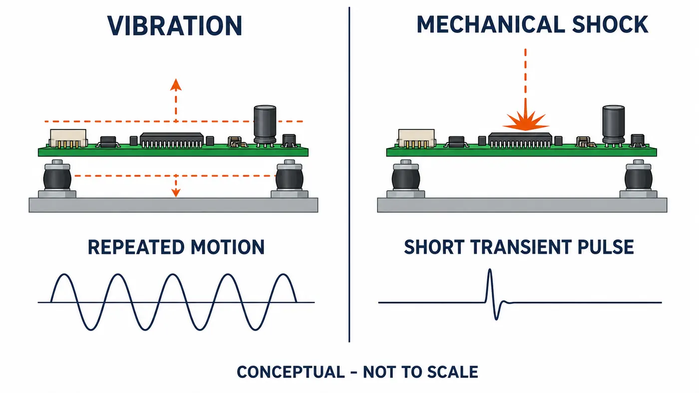
Conceptual comparison: vibration applies repeated motion, while mechanical shock is a short transient pulse. Not to scale.
Failure Modes: Which Test Is More Likely to Expose What?
The table below is a planning aid, not a claim that each failure belongs exclusively to one test. Board construction, component mass, mounting, frequency response, pulse shape and inspection method can move a failure from one category to another.
| Potential weakness | Vibration relevance | Shock relevance | Evidence to collect |
|---|---|---|---|
| Solder-joint fatigue | High under repeated cyclic strain | Possible under a severe transient | Live continuity, microscopy and targeted cross-section if justified |
| Pad cratering / pad-interface damage | Possible when repeated board flexure is high | Often important after rapid board bending | Optical inspection, electrical test and failure analysis |
| Heavy-component attachment | High near resonance or long exposure | High under inertia from an abrupt pulse | Response acceleration, visual inspection and attachment review |
| Connector intermittency | High with repeated micro-motion | High during a momentary separation event | High-speed continuity monitoring and connector inspection |
| Wire or lead breakage | High when unsupported motion repeats | Possible under abrupt displacement | Separate event channels and physical inspection |
| Fastener or support weakness | High under repeated motion | High at load transfer points | Torque witness, fixture response and post-test inspection |
| Board/enclosure interface | High if a structural mode amplifies motion | High where the pulse enters through mounts | Control and response accelerometers plus mechanical inspection |
Do not diagnose from a single open-circuit event alone. A broken monitoring wire can resemble a solder-joint failure. Separate channels, strain or response measurements, careful cable restraint and physical failure analysis improve confidence.
Test Inputs and Equipment Are Not Interchangeable
A useful test request states what must be reproduced and measured. “Test at 20 g” is incomplete for both vibration and shock.
For vibration, the laboratory normally needs the required vibration type, frequency range, level or spectrum, duration, axes, tolerances, control strategy and product operating state. Low-frequency motion can be displacement-limited, while high-frequency testing can be force- or acceleration-limited. The test system and fixture must handle the complete profile without uncontrolled resonances or excessive cross-axis motion.
For shock, the laboratory normally needs the pulse shape, nominal peak, duration, direction, number of pulses, tolerance and whether the unit is operating. The actual measured pulse must remain within the applicable specification. Sensor bandwidth and mounting must be suitable for the short event; a measurement chain chosen for low-level vibration may clip or distort a high-g transient.
Use the current, applicable edition of the product or customer standard. Public summaries help explain method boundaries, but they do not replace a purchased standard, contractual requirement or approved test specification.
Fixture, Mounting and Instrumentation Can Change the Result
The test article should be mounted in a way that represents its service installation or the governing test requirement. If the real PCB uses four standoffs but the laboratory clamps every edge, its modes and deflection can change. If a fixture resonates inside the test band, the board may receive an input different from the intended profile.
Five checks are especially important:
- Service mounting: Reproduce the relevant standoffs, rails, fasteners, enclosure interfaces and connector constraints.
- Fixture dynamics: Verify that fixture response is understood over the required band. A fixture mode can amplify or notch the input.
- Control location: Place the control accelerometer where the approved procedure defines the input, not where it merely produces a convenient reading.
- Response channels: Measure board or component response when local resonance, heavy components or sensitive interfaces are part of the risk.
- Sensor and cable installation: A soft mount can reduce high-frequency response; excessive sensor mass can change a small board; loose cables can inject force or create false electrical events.
Mounting design also affects the product outside the laboratory. Review how to mount a PCB in an enclosure when standoff position, clearance, grounding or support strategy is still open.
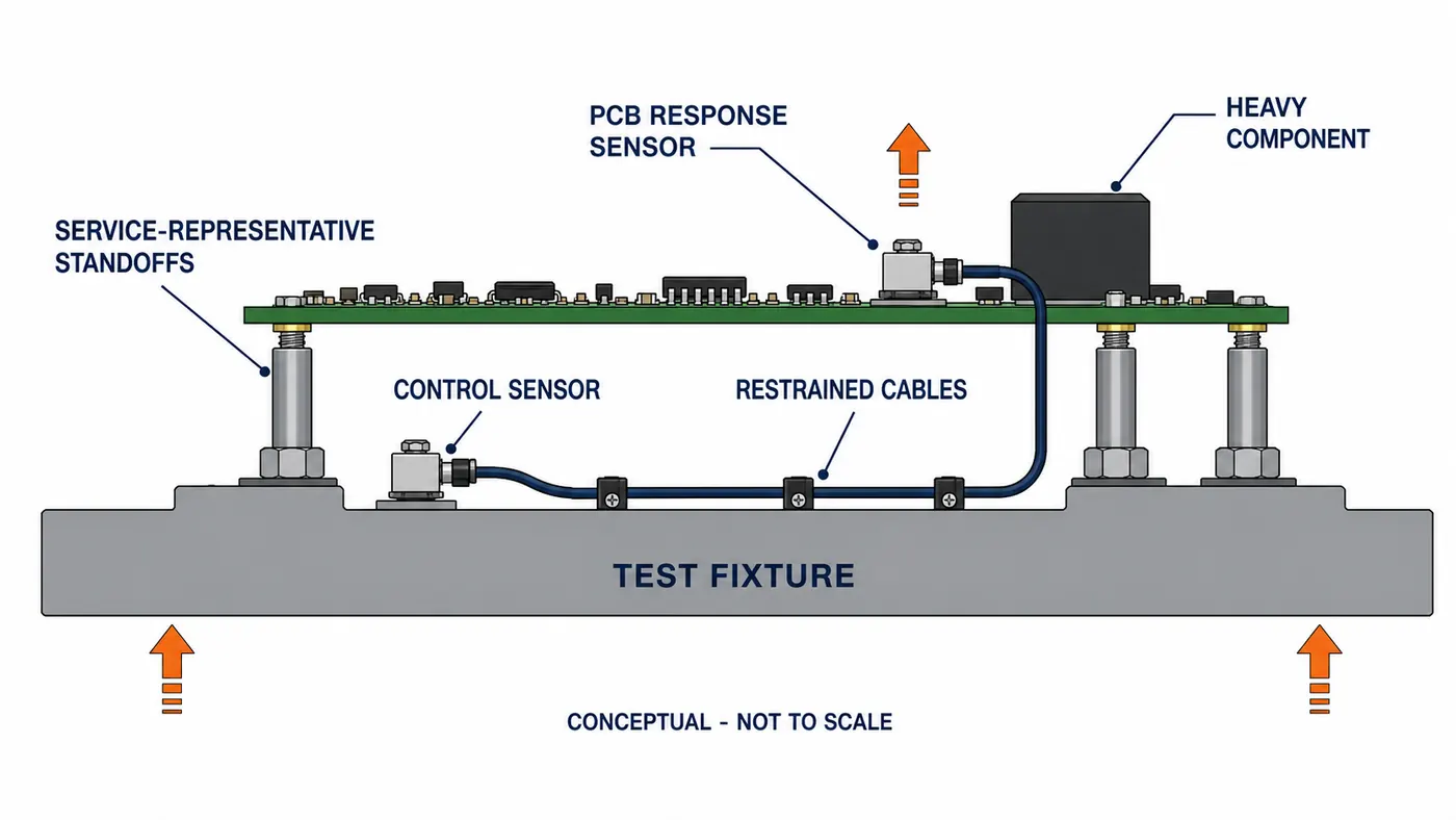
Conceptual fixture: the control sensor measures fixture input while the response sensor measures PCB motion. Not to scale.
PCB Vibration and Shock Test Plan Checklist
Start with the real environment, then trace each requirement to a test and an acceptance check.
- Define the life-cycle event. Separate manufacturing handling, packaged transport, installation, normal operation, maintenance drops and abnormal impacts.
- Identify the governing requirement. Record the product standard, customer specification, measured field profile or approved engineering rationale. Confirm the edition and any tailoring.
- Define the test article. State PCB revision, component population, enclosure, fasteners, cables, conformal coating or potting, and whether the sample is representative of production.
- Select vibration, shock or both. Use repeated service loads for vibration and discrete transient events for shock. Select both only when the life cycle contains both.
- Specify mounting and orientation. Document the fixture, service interfaces, axes, cable routing and any mass simulators.
- Specify exposure and tolerances. Use the governing requirement for frequency profile, pulse, duration, count and tolerances. Do not copy values from an unrelated product.
- Define operating state and monitoring. State powered/unpowered condition, functional loads, continuity channels, sample rate and allowable interruptions.
- Define inspection and acceptance. Include baseline checks, in-test limits, post-test electrical/functional checks, visual criteria and failure-analysis triggers.
- Review test order. Sequence can matter when cumulative damage is possible. Record why vibration or shock comes first and whether intermediate inspection is required.
- Approve the plan before testing. Design, reliability, quality, the laboratory and the customer should resolve ambiguous requirements before the sample is mounted.
This traceability prevents a common failure: a laboratory produces valid data for a profile that does not represent the product’s actual risk.
How to Monitor the Board and Define Pass or Fail
“No visible damage” is rarely a complete acceptance criterion for an operating assembly. Some cracks are hidden, and intermittent opens may disappear when the unit returns to the bench.
A defensible evidence package can combine:
- baseline visual, electrical and functional results;
- control acceleration and selected response channels;
- high-speed continuity on critical daisy chains, connectors or power paths;
- functional telemetry appropriate to the product;
- event timestamps correlated with the mechanical input;
- post-test visual inspection and electrical/functional retest; and
- targeted X-ray, microscopy, dye-and-pry or cross-section analysis when the approved failure-analysis plan calls for it.
Acceptance limits must come from the governing requirement. Examples of criterion categories include no unsafe condition, no prohibited functional interruption, no permanent parameter shift beyond specification, no loose hardware, no unacceptable cracking and successful post-test operation. The numerical threshold and allowed interruption duration are product-specific.
Circuit card assembly testing explains how AOI, X-ray, ICT and functional testing cover different defect classes. Those methods complement dynamic exposure; they do not replace it.
Published engineering scenario: separating a solder event from a wiring event
In the publicly available NASA-DOD Lead-Free Electronics Project vibration work, the problem was not merely whether an electrical event occurred. The team needed to distinguish a solder-joint failure from a broken monitoring lead, because both could appear as an open circuit to the event detector.
The treatment and action combined instrumented event detection with post-test visual inspection of soldered components and the signal wiring. The published report notes that some components detached during the escalating vibration work, while inspection did not find broken signal wires. That evidence helped keep a wiring artifact from being treated as the explanation for every detected event.
The reader lesson is bounded but useful: give monitoring wires their own restraint and inspection path, preserve event timing, and define how an electrical interruption will be confirmed physically. This published research used its own test vehicles and profile; it is not a PCBtry customer case and its vibration levels should not be copied into an unrelated product plan.
When You Need Vibration, Shock or Both
| Service evidence | Recommended starting point | Why |
|---|---|---|
| Continuous motor, fan, pump, engine or rail excitation | Vibration | Repeated excitation and resonance/fatigue dominate |
| A defined handling drop or abrupt impact | Mechanical shock | The event is a discrete transient pulse |
| Packaged transport plus operation near rotating machinery | Both, with separate traceable profiles | Transport impacts and operating vibration are different loads |
| Unknown field environment | Measure or obtain the requirement before setting severity | A generic profile may over-test or under-test the product |
| Concern is ESD, dielectric withstand or personnel safety | Neither test answers it | Use the applicable electrical-safety or ESD method |
Running both tests is not automatically more rigorous. It is only more relevant when both load types occur or the governing specification requires both. Extra exposure without a requirement can consume samples, obscure root cause and create a qualification result that is difficult to interpret.
Common Test-Planning Mistakes
- Copying a dramatic g-level from another product: correct it by tracing severity to the actual standard or field environment.
- Ignoring pulse duration or vibration frequency content: correct it by specifying the complete input, not one headline number.
- Treating the fixture as rigid without evidence: correct it with fixture review and response measurement where necessary.
- Using a sensor or mount outside its useful bandwidth: correct it through range, resonance, mounting and calibration checks.
- Testing a bare board when the enclosure controls the response: correct it by defining a representative test article.
- Failing to monitor intermittency: correct it with suitable live electrical channels and sample rate.
- Leaving pass/fail until after exposure: correct it by approving acceptance criteria in the plan.
- Calling ESD or electrical safety a mechanical shock test: correct the discipline and select the applicable electrical method.
PCB Vibration vs Mechanical Shock FAQ
Is mechanical shock the same as electrical shock on a PCB?
No. Mechanical shock is a transient physical load. Electrical shock refers to hazardous electrical energy, while ESD is a fast electrostatic discharge. They require different test methods and acceptance evidence.
Is shock testing just high-g vibration testing?
No. Shock is defined by a transient pulse and its duration, shape and direction. Vibration is repeated oscillatory loading described over frequency and time. Peak acceleration alone cannot make them equivalent.
Can a PCB pass vibration testing and still fail shock testing?
Yes. A board may tolerate repeated vibration but suffer excessive deflection or connector interruption during a short pulse. The reverse can also occur when a board survives discrete impacts but accumulates fatigue near resonance.
Should PCB vibration testing use sine or random vibration?
Use the method required by the applicable specification or supported by the service environment. Sine and random vibration answer different questions and should not be substituted without technical justification.
How many axes should be tested?
The governing specification defines the axes and orientations. Three orthogonal axes are common in dynamic testing, but the exact setup must reflect the requirement, product mounting and likely load directions.
What is more important in a shock test: peak g or pulse duration?
Neither should be considered alone. Peak acceleration, duration, pulse shape, velocity change, direction, tolerance and structural response together describe the event.
Why monitor electrical continuity during vibration or shock?
Momentary connector, solder-joint or lead interruptions may not remain after the test. Live monitoring can capture the event and correlate it with the mechanical input, provided wiring artifacts are controlled.
Can a bare PCB be tested without its enclosure?
It can be tested when the requirement defines that specimen, but it may not represent system response. Enclosure supports, standoffs, connectors, cables and heavy components can change board modes and load paths.
Which PCB areas should be inspected after dynamic testing?
Prioritize heavy components, area-array packages, connectors, mounting holes, board edges, stiffener transitions, large unsupported spans, cables and any location where response or strain was high. The approved inspection plan should define the method and acceptance criteria.
Do all PCB products need both vibration and shock qualification?
No. The choice depends on the life-cycle environment and governing requirement. Use both when repeated and transient loads are credible or required, not simply because two tests sound more comprehensive.
Plan the Dynamic Test Around the Real Service Environment
Before asking for a quotation or laboratory slot, prepare the PCB revision, assembly drawing, stackup where relevant, enclosure and mounting details, component mass concerns, cable configuration, operating state, applicable standard, field-load evidence, axes, monitoring channels and pass/fail criteria.
PCBtry can review PCB fabrication and assembly information for manufacturability and mechanical-risk discussions, but a qualified laboratory and the applicable product authority must approve and execute the vibration or shock test. Send a defined environment and acceptance requirement—not only a g-level—so the design, fixture and verification plan can be reviewed on the same technical basis.



0 Comments