




A plated through hole (PTH) is a drilled hole whose wall is metallized so it can connect copper layers and, when required, accept a component lead. The difficult part is not making the hole conductive once; it is producing a continuous, well-bonded copper barrel that survives soldering and repeated temperature change without voids, separation or cracks.
The manufacturing route therefore links CAM review, drilling, smear removal, chemical activation, electroless copper, electrolytic copper and inspection. For an engineering review and quotation, send the Gerber or ODB++ data, NC drill file, stackup, material, finished board thickness, finished-hole sizes and tolerances, copper requirements and acceptance or reliability requirements.
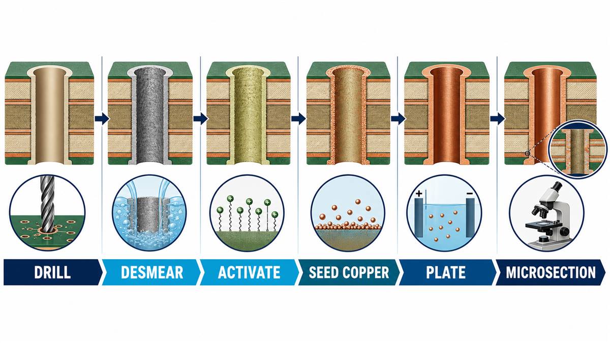
What Is the PCB Plated Through-Hole Process?
The PCB plated through-hole process converts an insulating drilled wall into a copper-lined electrical interconnect. Mechanical drilling exposes resin, glass fiber and the edges of internal copper pads. Cleaning and desmear prepare that mixed surface; a thin chemical copper deposit makes it conductive; electroplating then builds the functional copper barrel.
PTH fabrication is different from through-hole assembly. Fabrication creates the copper barrel in the bare board. Assembly later inserts and solders a lead. A via may use the same basic metallization route but normally serves layer interconnection rather than component insertion.
How Does the PCB Plated Through-Hole Process Work?
The sequence below shows what each stage must achieve, what engineers should review and what can fail. Exact chemistry, dwell time and acceptance values belong to the approved fabrication specification—not a universal web recipe.
1. CAM, stackup and drill-data review. Engineering checks the NC drill file against the copper artwork, finished-hole callouts, tolerances, board thickness and layer registration. The review distinguishes plated from non-plated holes and identifies press-fit holes, plated slots and controlled-depth features. If the finished diameter is mistaken for the production drill diameter, plating buildup can leave a component hole undersized; weak annular-ring allowance can make normal drill movement expose or break an internal connection.
2. Panel drilling. CNC machines drill the laminated production panel with controlled tool condition, entry/backup materials, spindle behavior and stack height. The goal is a correctly located, round wall without excessive burrs, glass breakout, nail heading or heat damage. A worn or overloaded drill can tear glass bundles and roughen the wall, making later cleaning and copper coverage less predictable.
3. Deburring, cleaning and desmear. Drilling can smear softened resin over the exposed edge of an internal copper layer. Desmear removes that film and conditions the hole wall so copper can bond to both dielectric and inner-layer copper. Under-cleaning can leave a high-resistance or intermittent interface; over-aggressive treatment can attack resin, increase roughness or create excessive etchback. The correct judgment comes from process coupons and microsections, not from how clean the panel looks from the surface.
4. Conditioning, activation and acceleration. The nonconductive wall is cleaned and chemically prepared so a catalytic layer reaches the full depth of the hole. Coverage inside a small, deep hole is harder than on an open surface because solution exchange and trapped air matter. Incomplete activation creates skips that remain as plating voids after later copper buildup.
5. Electroless copper deposition. A thin continuous copper seed layer is deposited without external current. Its job is to connect the entire hole wall electrically for the next plating stage. The deposit must cover the center of the barrel and the inner-layer interfaces; a bright ring at the hole mouth does not prove full-depth continuity.
6. Electrolytic copper buildup. The conductive panel becomes the cathode and copper thickness is built on the hole wall and panel surface. Current distribution, agitation, bath condition, panel loading and hole geometry affect throwing power—the ability to deposit copper in recessed locations. Poor distribution can leave the hole center thin while the surface and hole knee look heavy, producing a latent thermal-fatigue risk.
7. Circuit imaging, pattern plating and etching integration. Depending on the chosen fabrication flow, the PTH barrel must remain protected while the external circuit is imaged, plated and etched. Resist voids, poor plating adhesion or an uncontrolled etch can damage the connection between surface pad and barrel. Engineering should review copper wrap, annular ring and finished dimensions as part of one interconnect, not as unrelated measurements.
8. Inspection, electrical test and reliability evidence. Finished boards receive dimensional checks and electrical continuity/isolation testing. Microsections of representative coupons reveal hole-wall copper distribution, voids, cracks, inner-layer separation, smear and registration. When the product requires it, thermal stress or cycling is used to challenge the copper barrel and interfaces. A continuity pass alone cannot reveal every thin or mechanically weak barrel.
Which Inputs Control PTH Manufacturability?
Manufacturability is determined by the relationship between the hole and the board, not by drill diameter alone. The supplier needs the finished board thickness and finished-hole requirement together because plating and surface finish change the final opening.
| Input | Why it matters | What to state in the RFQ |
|---|---|---|
| Finished hole size and tolerance | Controls lead fit, press-fit behavior and production drill compensation | Finished—not nominal drill—diameter and tolerance |
| Board thickness and hole depth | Sets the depth-to-diameter challenge for cleaning and plating | Finished thickness, stackup and smallest plated hole |
| Annular ring and layer registration | Determines whether drill movement still leaves a reliable copper connection | Pad sizes, drill-to-copper rules and acceptance class |
| Material and z-axis behavior | Thermal expansion strains the copper barrel | Approved laminate system and thermal exposure |
| Copper and reliability requirement | Defines plating and acceptance evidence | Drawing/specification reference and required coupon tests |
Why Do Aspect Ratio and Throwing Power Matter?
Aspect ratio is commonly expressed as hole depth divided by drilled diameter. As the hole becomes deeper or narrower, drills are harder to evacuate cleanly and process solutions exchange less freely. During electroplating, the hole center can receive less copper than the surface. That distribution problem is described by throwing power.
Do not approve a design from a generic aspect-ratio number alone. Ask the fabricator to evaluate the actual material, panel construction, smallest hole, copper requirement and inspection plan. A feature inside nominal capability may still carry lower margin when several difficult conditions occur together.
What PTH Defects Reveal About the Process
| Defect or signal | Likely process area | Why it matters | Useful evidence |
|---|---|---|---|
| Resin smear at inner copper | Drilling/desmear | Blocks a sound barrel-to-inner-layer connection | Axial or transverse microsection |
| Copper plating void | Cleaning/activation/electroless copper | Creates an open or locally weak conductor | Microsection plus electrical test |
| Thin copper at barrel center | Electroplating distribution | Raises resistance and thermal-fatigue risk | Measured coupon distribution |
| Inner-layer separation | Surface preparation/plating/thermal stress | Can become intermittent after soldering or cycling | Microsection after specified stress |
| Barrel or corner crack | Copper ductility, geometry and thermal strain | May pass initially and open in service | Thermal cycling with resistance monitoring and sectioning |
| Insufficient annular ring | CAM allowance/drilling/registration | Reduces the copper connection around the hole | Registration and cross-section review |
How Does Design Affect PTH Reliability?
A thicker board, smaller hole and larger thermal excursion generally place more strain on the plated barrel. Material z-axis expansion, plated-copper properties, layer count, internal pad geometry and assembly heat exposure also affect the result. This is why a PTH that survives room-temperature electrical test can still fail during soldering or later temperature cycling.
Keep finished-hole tolerances realistic, provide adequate pads, avoid stacking difficult drill and copper-clearance conditions, and identify press-fit or repeated thermal-cycle applications early. For the upstream hole-formation context, review the PCB drilling process; for assembly implications, see the through-hole assembly guide.
What Tests Should a Buyer Request?
Match evidence to the product risk. Electrical testing is necessary for continuity and isolation, but destructive cross-sectioning is the direct way to examine the barrel, interfaces and registration. Thermal stress or cycling adds evidence that those structures remain stable after expansion and contraction.
- Finished-hole and board-thickness measurement against the drawing.
- Electrical continuity and isolation coverage appropriate to the netlist.
- Coupon microsection showing representative PTH geometry and copper distribution.
- Defect acceptance tied to the ordered specification and product class.
- Specified thermal stress/cycling and resistance monitoring for reliability-critical builds.
- Lot traceability for material, process panel and inspection records where required.
Our broader PCB testing guide explains why no single inspection method covers every failure mode.
How Should You Compare PTH Suppliers?
Ask for evidence that matches your feature, not a generic capability table. A useful engineering response should identify the smallest finished plated hole, actual finished thickness, aspect-ratio challenge, material, tolerance chain, coupon plan and any special thermal requirement. It should also distinguish standard production from a feature that needs engineering approval.
- Will you review finished-hole size rather than only the NC drill diameter?
- How will you verify desmear and inner-layer connection?
- Where is hole-wall copper measured on the coupon?
- Which void, crack, separation and annular-ring criteria govern acceptance?
- What electrical and thermal evidence will be included with the lot?
Frequently Asked Questions
Is a plated through hole the same as a via?
Both can use a copper-plated barrel to connect layers. A via normally serves interconnection, while a component PTH also needs a finished opening and tolerance suitable for a lead or press-fit pin.
Why is the production drill larger than the finished hole?
Copper plating and final surface processing reduce the opening. The fabricator selects a production drill that targets the specified finished diameter and tolerance.
What does desmear remove?
It removes resin deposited on the drilled wall and exposes clean internal copper interfaces. Incomplete smear removal can leave an electrically weak or separated connection.
Why is electroless copper needed?
The drilled dielectric wall is not conductive. Electroless deposition creates a continuous seed layer so electrolytic copper can be built through the full hole.
Can electrical test prove that a PTH is reliable?
It proves the tested nets meet continuity/isolation criteria at that time. It does not directly show thin copper, poor interfaces or every latent crack risk, so microsection and thermal evidence may also be needed.
What causes PTH barrel cracks?
Barrel cracks are associated with the strain created when the board expands through its thickness while the copper barrel restrains that movement. Geometry, laminate behavior, copper properties, plating distribution and thermal exposure all contribute.
What files are needed for a PTH quotation?
Send Gerber or ODB++, NC drill data, fabrication drawing, stackup, material, finished thickness, plated/non-plated definitions, finished-hole sizes and tolerances, copper requirements and acceptance/test specifications.
Should every PTH build require thermal cycling?
No. The test plan should follow product risk, service environment and the ordered specification. Reliability-critical or difficult geometries justify stronger evidence than a routine low-risk board.
Request a PTH Manufacturability Review
Before release, submit your Gerber or ODB++ package, NC drill file, stackup, fabrication drawing and PTH acceptance requirements. A focused review can identify hole-size compensation, annular-ring, aspect-ratio, material and inspection issues before they become plating defects or component-fit problems.



1 Comment
PCB Routing Process: Toolpaths, Edge Quality and Inspection Checks - thindry pcb manufacturer · 09/01/2026 at 16:50
[…] Use one authoritative profile and state which file governs if data disagree. For the preceding hole operation and its relationship to NC data, see our plated-through-hole process guide. […]