




The PCB underfill process places a polymer beneath a BGA, CSP, flip-chip or similar package so the cured material shares mechanical and thermal stress with the solder joints. Underfill is used when drop, vibration, thermal cycling or package-to-board expansion mismatch creates more risk than the solder array should carry alone. It is not a universal coating: material selection, package gap, board cleanliness, dispensing access, flow and cure must work as one qualified process.
For an engineering review, send PCBTRY the Gerber or ODB++ data, BOM, package datasheets, assembly drawing, underfill keep-outs, operating environment, reliability target, rework policy and inspection requirements. These inputs allow the team to review dispensing access, neighboring component clearance, material compatibility and test evidence before quotation.
What Is the PCB Underfill Process?
Underfill is an assembly-level reinforcement process performed after the target component has been soldered and electrically verified. A capillary material is normally dispensed along one or more package edges and drawn into the gap around the solder joints. After the fill pattern is confirmed, controlled curing converts the liquid into a bonded support structure.
How Does the PCB Underfill Process Work?
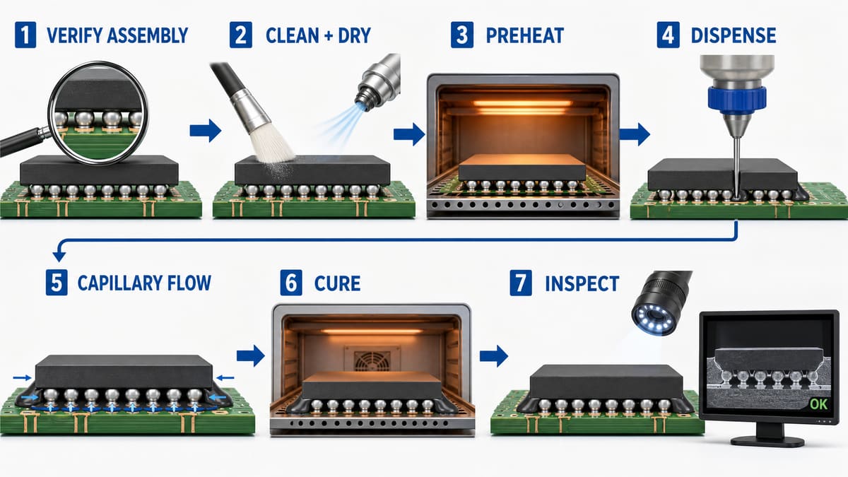
1. DFM and material review. Engineering confirms the package, standoff gap, board finish, component neighborhood, dispense path, keep-outs and approved material. A material that flows well may still be unsuitable if its cure, modulus, expansion behavior, storage or rework characteristics conflict with the product.
2. Solder-joint verification. Placement, reflow and required inspection or electrical checks are completed before underfill. Encapsulating a skewed package, open joint or unacceptable void condition converts an assembly defect into an expensive removal problem.
3. Cleaning and drying. The package edge and board must meet the material supplier’s cleanliness and moisture conditions. Residue, oil or trapped solvent can disturb wetting, adhesion and cure. Cleaning is therefore selected from the flux/material combination, not applied as a generic step.
4. Preheat and fixture control. When the qualified process requires it, the assembly is brought to a controlled condition that supports repeatable viscosity and capillary flow. Board support prevents movement while preserving access to the package edges.
5. Dispensing. Equipment places a controlled amount of material at a defined edge and distance. Needle position, dispense speed, shot volume and material condition affect whether the bead feeds the gap or spreads into keep-outs.
6. Capillary flow and fillet formation. The liquid travels beneath the package and around solder joints. Operators monitor flow-front behavior and the external fillet. Dispensing too aggressively can trap air; insufficient volume can leave an incomplete fill; excessive material can contaminate adjacent components or test points.
7. Cure. The assembly follows the approved time/temperature route for that exact material and product. The objective is complete, consistent cure without exceeding component, laminate or solder-joint limits. A generic oven setting is not evidence of cure.
8. Inspection and release. Visual inspection checks fillet continuity, overflow and contamination. X-ray, acoustic microscopy, sectioning or reliability tests may be specified when internal voids or adhesion are critical. The method must match the failure risk and customer acceptance criteria.
Which Underfill Material Should Be Used?
| Decision factor | Why it matters | What to confirm |
|---|---|---|
| Flow and viscosity | Controls ability to enter the real package gap | Qualified dispense and preheat window |
| Cure route | Affects throughput and component heat exposure | Approved cure evidence for the assembly |
| CTE and modulus | Changes stress transferred among package, joints and PCB | Application-specific reliability rationale |
| Adhesion and compatibility | Residues and surfaces can weaken bonding | Flux, finish, mask and cleaning compatibility |
| Reworkability | Determines whether a failed package can be removed economically | Customer repair policy and demonstrated method |
What Design Details Affect Underfill Flow?
Package gap, solder-mask geometry, nearby passives, via structures, board warpage and dispenser access shape the flow path. Tall fillets or components positioned close to the package can block the needle or redirect material. Add underfill keep-outs and inspection access to the assembly drawing instead of leaving the factory to infer them.
What Causes Voids and Incomplete Fill?
| Observed issue | Possible cause | Engineering response |
|---|---|---|
| Flow stops before opposite edge | Insufficient material, low wetting or obstructed gap | Review material condition, volume, temperature and geometry |
| Internal void indication | Air entrapment, dispense sequence or contamination | Verify with the specified internal inspection method |
| Irregular external fillet | Board level, needle position or inconsistent flow | Check fixture, path and equipment repeatability |
| Overflow into keep-out | Excess volume or poor barrier/clearance planning | Correct the recipe and assembly drawing constraints |
| Delamination after stress | Surface contamination, material mismatch or cure issue | Review adhesion preparation, cure record and test condition |
How Does Underfill Affect Rework and Repair?
Underfill can improve mechanical robustness while making component removal slower and riskier. Heat and mechanical force used during removal may damage pads, solder mask or neighboring parts. Decide whether rework is permitted before material approval, and require a documented removal, site-cleaning, replacement and retest route where serviceability matters.
How Is Underfill Quality Inspected?
No single inspection proves every attribute. Visual inspection evaluates the accessible fillet and overflow. X-ray may reveal density changes but can have interpretation limits; acoustic methods can help evaluate internal interfaces; destructive sectioning provides detailed evidence but consumes samples. Reliability testing should reproduce the actual mechanical and thermal risk rather than use an unrelated test for appearance.
What Evidence Should Buyers Request?
- Approved material identity, storage and handling record.
- First-article dispense pattern and external fillet acceptance.
- Verified cure settings and lot traceability.
- Defined internal inspection scope when voids are critical.
- Pre-underfill solder-joint and electrical verification.
- Rework disposition and post-repair test requirements.
How Do You Choose an Underfill Process Supplier?
Compare engineering review, dispensing repeatability, material control, cure verification, internal inspection access and repair documentation—not merely whether a supplier owns a dispenser. Ask how recipes are locked, how material life is tracked, what happens after a flow anomaly and which evidence accompanies the first article.
Frequently Asked Questions
Is underfill applied before or after reflow?
Capillary underfill is normally applied after soldering and the required joint/electrical checks. Other package technologies may use different material routes, so identify the exact process.
Does every BGA need underfill?
No. Use depends on package construction, board design, mechanical and thermal exposure, reliability target and service policy.
Can underfill repair a bad solder joint?
No. Underfill can reinforce a sound assembly but should not conceal an open, bridge, skewed package or unacceptable solder condition.
What files are needed for quotation?
Provide PCB data, BOM, assembly drawing, package data, keep-outs, environment, material preference, inspection and reliability requirements.
Can an underfilled BGA be reworked?
Sometimes, but feasibility depends on material, package, layout and approved procedure. Rework can add heat and pad-damage risk.
How are underfill voids detected?
Use the inspection method defined for the risk, which may include X-ray, acoustic inspection or destructive analysis. Visual fillet checks cannot prove the entire internal fill.
Why is preheating used?
When specified by the qualified process, controlled preheat can stabilize viscosity and support capillary flow. It must remain within material and component limits.
What should a first-article report include?
At minimum, identify material and lot, process settings, pre-underfill verification, fillet result, specified internal inspection and disposition.
Request an Underfill Process Review
Send PCBTRY your PCB/assembly package, component datasheets, keep-outs, operating environment, reliability target and rework policy. We can review material-route fit, dispensing access, inspection evidence and RFQ gaps before production.



0 Comments