




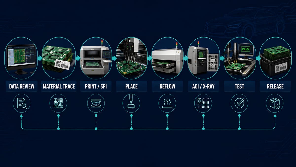
The automotive rigid PCB assembly process converts a fabricated rigid board into a controlled electronic assembly through data review, material verification, solder-paste printing, component placement, reflow or selective soldering, inspection, testing and documented release. Compared with a general-purpose build, the manufacturing route must be tied more closely to the vehicle function, expected temperature, vibration, moisture, electrical loads, service life and customer-specific acceptance plan.
PCBTRY can review Gerber files, BOM, CPL/centroid data, assembly drawings, test requirements and traceability expectations before quotation. Sending these inputs together allows engineering review to identify footprint, polarity, thermal, mechanical and test-access risks before they become repeated production defects.
What Is an Automotive Rigid PCB Assembly Process?
It is a repeatable PCBA manufacturing route for components mounted on a non-flexing printed circuit board intended for an automotive electronic product. “Automotive” is not created by using one special solder paste or adding a final inspection. The required controls come from the product’s actual function, risk classification, customer specifications, qualification plan and supply-chain requirements.
What Must Be Defined Before Automotive PCB Assembly Starts?
The assembly supplier needs a controlled release package. Missing information forces production staff to make assumptions that can break traceability or validation.
| Input | Decision it controls | Typical release risk |
| Gerber/ODB++ and drill data | Board revision, pad geometry and tooling | Assembly data does not match the fabricated PCB |
| BOM with approved MPNs | Component identity and substitutions | Unapproved package, grade or lifecycle change |
| CPL/centroid file | Placement position, side and rotation | Polarity or rotation error repeated by the machine |
| Assembly drawing | Orientation, hand-fit parts and special notes | Ambiguous connector or mechanical installation |
| Test specification | Coverage, limits, fixtures and data retention | A board “passes” without proving required functions |
| Traceability plan | Lot, material, process and result linkage | A field issue cannot be bounded to affected units |
How Does the Automotive Rigid PCB Assembly Process Work?
1. Engineering review and risk classification. The supplier reconciles fabrication data, BOM, CPL, drawings, process notes and test requirements. Engineers flag polarity, package, creepage, thermal mass, heavy-component, connector and test-access risks. A signed release package prevents the automated line from faithfully building the wrong revision.
2. Incoming material control. Bare boards and components are checked against approved part numbers, lot information, storage and handling requirements. Moisture-sensitive devices, finish condition and package damage need defined reactions. A label alone is not evidence if it cannot be linked to receiving and production records.
3. Kitting, programming and line setup. Feeder positions, component lots, stencil, support tooling, programs and work instructions are verified. Pre-programmed devices require firmware/revision control; in-circuit programming requires accessible interfaces and a recorded pass result.
4. Solder-paste printing and SPI. Stencil design, board support, paste condition, alignment, cleaning and print settings determine deposit geometry. SPI detects missing, shifted or abnormal deposits early. The useful control is a reaction rule that corrects the printer before a trend becomes a lot-wide defect.
5. Automated placement and first-article verification. Vision systems place components from the approved CPL and package library. Feeder verification, polarity checks and first-article comparison catch wrong parts, rotations, nozzle damage and coordinate errors before volume release.
6. Reflow soldering. A measured profile is developed for the assembly’s thermal mass, component limits, solder system and board construction. An oven recipe name is not enough; profile evidence should show that representative locations were measured and approved.
7. Through-hole and special processes. Connectors, relays, transformers or other odd-form parts may use wave, selective or manual soldering. Lead protrusion, solder fill, thermal exposure, fixtures and masking require separate acceptance rules. Large parts may also need mechanical retention defined by the product design.
8. Cleaning, coating or encapsulation when specified. Residue, cleanliness, masking, cure and coverage affect adhesion and long-term environmental protection. These processes are not automatic automotive requirements; they must match the application and validation plan.
9. Inspection, electrical test and functional test. AOI checks visible placement and joint features; X-ray can examine hidden joints; ICT or flying probe checks electrical nodes where designed; functional test exercises product behavior. No single method covers every failure mode.
10. Final release and traceability. The lot is released against approved visual, electrical, functional and documentation criteria. Records link board revision, component lots, process route, inspection, rework and test results to the shipped unit or defined batch.
Which Process Controls Prevent Repeat Defects?
The strongest controls detect drift close to its source and define what happens next.
| Control point | Risk detected | Evidence buyers can request |
| Revision reconciliation | Mixed Gerber, BOM, CPL or firmware | Released package and change record |
| SPI trend review | Paste-volume or alignment drift | Inspection results and reaction rule |
| First article | Wrong part, package, polarity or rotation | Approved comparison record |
| Reflow profiling | Insufficient wetting or excessive thermal exposure | Measured profile for representative assembly |
| AOI/X-ray disposition | Visible or hidden-joint anomalies | Program, defect classification and review record |
| Rework control | Unapproved repair or excess thermal cycles | Authorization and unit-level rework history |
How Do Design Choices Affect Assembly Reliability?
Assembly reliability starts with pad geometry, component selection, copper balance, thermal paths, mechanical support and test access. Heavy components near high board deflection can load solder joints during vibration. Large thermal-mass differences can widen the reflow process window. Inaccessible nodes make faults harder to isolate, while crowded connectors can hide workmanship defects.
Review the PCB together with its housing, heatsink, fasteners and cable loads. A rigid board still bends under installation and vibration. The module boundary conditions—not the bare PCB alone—determine many mechanical stresses.
What Inspection and Validation Does an Automotive PCBA Need?
The correct plan is product-specific. Separate production screening from design qualification: production tests look for manufacturing escapes, while qualification demonstrates that the design and process can survive defined use conditions.
| Method | What it can show | What it does not prove alone |
| SPI/AOI | Paste and visible assembly features | Hidden-joint integrity or complete function |
| X-ray | Hidden-joint structure and selected internal anomalies | Electrical performance or lifetime |
| ICT/flying probe | Accessible electrical nodes and component checks | All real operating conditions |
| Functional test | Defined behavior at specified conditions | Environmental durability unless combined with stress |
| Thermal/vibration/environmental validation | Response to program-defined stresses | Every possible vehicle installation or misuse |
How Should Traceability and Change Control Work?
Traceability should let a team move from a shipped unit or batch back to the board revision, BOM revision, approved substitutes, component lots, manufacturing route, inspection results, firmware and rework history. The required granularity depends on the program; more data is not automatically better if records cannot be retrieved and used.
Change control must cover materials, components, process programs, fixtures, test software and approved repairs. Ask who approves a change, how affected work is identified and what revalidation is triggered.
What Common Failures Occur During Automotive PCB Assembly?
- Wrong or mixed revisions caused by disconnected release files.
- Paste defects that create opens, bridges or unstable joint volume.
- Polarity, package or feeder errors repeated across a production run.
- Thermal-profile mismatch around high-mass connectors or power devices.
- Hidden-joint anomalies without adequate inspection coverage.
- Residue, coating voids or masking errors where environmental protection is specified.
- Mechanical strain from connectors, fasteners, housings or heavy parts.
- Tests that record “pass” without controlled limits or failure diagnostics.
How Long Does Automotive Rigid PCB Assembly Take?
Lead time depends on component availability, board fabrication, tooling, first-article approval, programming, test-fixture readiness, special processes and qualification requirements. A prototype can be physically assembled quickly yet remain unreleasable while test limits, software or customer approvals are incomplete. Ask suppliers to separate material, engineering, production and validation time in the schedule.
How Do You Choose an Automotive PCB Assembly Supplier?
Evaluate the supplier against the specific program, not a generic automotive claim. Ask:
- How are Gerber, BOM, CPL, drawings, firmware and revisions reconciled?
- Which process data and traceability records are retained, and for how long?
- How are SPI, AOI and X-ray limits created, reviewed and changed?
- How are profiles measured and approved for thermally different assemblies?
- Who can authorize substitutions, deviations and rework?
- Which tests are production screens, and which support qualification?
- How are failures analyzed and corrective actions verified?
- Which certifications and customer approvals apply to the actual manufacturing site and scope?
Frequently Asked Questions
Is every automotive PCB assembly made to the same standard?
No. Requirements depend on product function, customer, market, risk and manufacturing location. The project specification and approved quality plan control the build.
Does IATF 16949 certification approve a specific PCBA?
No. A quality-management certification and a product’s design, process and validation approval are different evidence. Verify the certificate scope and the program-specific controls.
Are automotive-grade components enough to make the assembly reliable?
No. Component qualification does not replace PCB design, solder-process control, mechanical integration, cleanliness, testing or system validation.
When is X-ray inspection needed?
It is useful for hidden joints such as BGA or bottom-terminated packages when the inspection plan requires it. X-ray coverage and acceptance criteria must be defined; the presence of a machine is not proof of adequate control.
What files are needed for quotation?
Send fabrication data, BOM, CPL, assembly drawings, specifications, quantity, test requirements, firmware/programming needs and traceability expectations.
Can prototypes use the same process as production?
They can use representative materials and controls, but tooling, inspection sampling and test fixtures may differ. Record differences so production risks are not hidden by prototype success.
How should reworked boards be handled?
Use approved instructions, trained personnel, controlled thermal exposure and unit-level records. The acceptance and reuse of reworked assemblies must follow the program rules.
What is the best evidence of process control?
Look for linked records: approved input revisions, first article, process measurements, inspection results, test data, nonconformance disposition and change history.
Request an Automotive PCBA Engineering Review
Send PCBTRY your Gerber files, BOM, CPL, drawings, quantity, application conditions, test plan and traceability requirements. Request an engineering review and quotation to identify assembly, inspection and release risks before production.



0 Comments