




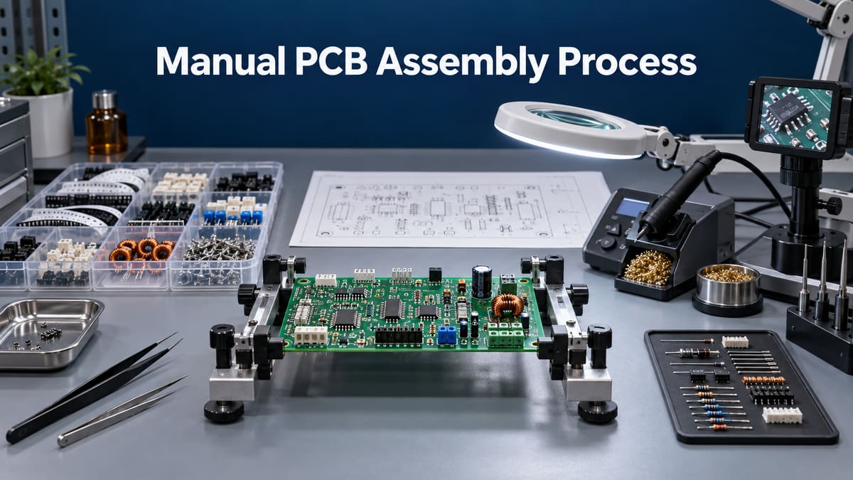
The manual PCB assembly process uses trained operators and controlled work instructions to place, solder, inspect and test components that are unsuitable or uneconomical for a fully automated route. It is common for prototypes, engineering builds, low-volume products, odd-form connectors, wiring, mixed SMT/THT assemblies, late-stage modifications and rework. Manual does not mean informal: material identity, polarity, heat exposure, workmanship, cleaning, traceability and test results still require documented controls.
pcbtry supports DFM, component/BOM review, prototype and mixed-technology assembly planning, inspection and test coordination. Send Gerber or ODB++ data, BOM, CPL, drawings, quantities, solder/cleaning requirements and test instructions for an engineering review and quotation.
What Is Manual PCB Assembly?
Manual PCB assembly is a production method in which an operator performs one or more assembly operations by hand, such as component preparation, insertion, placement, soldering, wiring, hardware installation, inspection or touch-up. A board may still use automated paste printing, pick-and-place or reflow for suitable SMT parts while reserving manual work for THT and odd-form components.
The route should be selected by package geometry, volume, access, thermal sensitivity, tooling cost, change frequency and required repeatability. A hidden thermal pad, dense fine-pitch array or high-volume repetitive operation may need a controlled machine process even when an experienced technician can build one sample manually.
For the wider routing context, compare this focused manual workflow with the complete PCB assembly process.
When Should You Use Manual Instead of Automated Assembly?
Use manual operations where flexibility and human access outweigh cycle-time and variation risks. Use automation where repeatable deposit, placement or thermal control is central to yield.
| Route | Best fit | Main control | Buyer question |
|---|---|---|---|
| Fully manual placement and hand soldering | Very low quantity, large accessible packages, development changes | Work instruction, operator qualification, joint-by-joint inspection | Which packages or hidden joints are outside a reliable hand process? |
| Manual placement plus controlled reflow | Small SMT builds where stencil/tooling choices are limited | Paste deposit, polarity, placement accuracy and reflow profile | How are paste volume and first-article placement verified? |
| Automated SMT plus manual THT/odd-form | Mixed boards with connectors, transformers, switches or wiring | Sequence, secondary heat exposure, access and mechanical support | Which operation covers every component group? |
| Selective/wave solder instead of manual THT | Repeat quantities with accessible and compatible THT population | Nozzle/pallet or wave design, thermal profile and keep-outs | At what volume and geometry does automation reduce variation? |
How Does the Manual PCB Assembly Process Work?
The workflow below treats manual assembly as a controlled traveler, not a series of improvised solder joints.
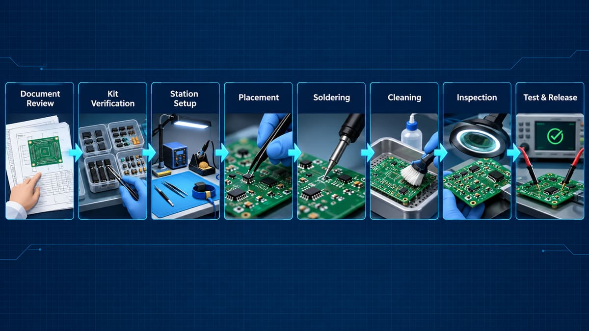
Step 1: Engineering and document review. Engineering reconciles the BOM, CPL, Gerber/ODB++, schematic, assembly drawing, polarity/orientation, approved substitutes, solder alloy, flux, cleaning rule, programming and test requirements. Conflicting revisions or unclear depictions must be resolved before kitting.
Step 2: Material receiving and kit verification. Components and bare boards are checked for part number, quantity, lot/date information where required, package, value, moisture/handling condition and visible damage. Repacked parts and look-alike polarized devices need positive identification. A shortage or substitute is held for approval rather than silently fitted.
Step 3: Workstation and tooling setup. The station is prepared for ESD, lighting, magnification, fume extraction, temperature-controlled soldering, tip geometry, fixtures and calibrated/verified tools as required. The selected solder and flux must be compatible with the finish, component, cleaning process and product requirements.
Step 4: Component preparation and placement. Leads are formed only within component and workmanship limits; components are inserted or placed according to the controlled drawing. Operators verify reference designator, value, polarity, pin 1, orientation, seating, standoff and mechanical support. Excessive lead-forming force can damage the seal or transfer stress to the plated hole.
Step 5: Controlled soldering. The method heats the termination and land together so solder wets both surfaces, then allows the joint to solidify without movement. Tip selection, heat capacity, contact time, flux activity and solder quantity are matched to the joint. A larger ground connection often needs better heat transfer, not an arbitrary temperature increase.
Step 6: Secondary assembly and cleaning. Wiring, connectors, hardware, heat sinks, staking or other approved operations follow the defined sequence. Flux residue is cleaned only with a validated chemistry and process; “no-clean” does not automatically mean residue is acceptable for every coating, high-impedance or harsh-environment product.
Step 7: Inspection and controlled rework. Visual inspection verifies identity, orientation, solder wetting, fillet, bridges, solder balls, contamination, lead protrusion, hardware and damage against the specified acceptance criteria. Hidden or inaccessible joints may need X-ray or another method. Rework is recorded and limited because repeated heating can lift pads, weaken barrels or damage components.
Step 8: Electrical test, functional test and release. The test plan may include shorts/opens screening, programming, boundary scan, ICT/flying probe support, functional test or application-specific checks. The traveler closes component deviations, inspection results, rework and test records before labeling, packaging and shipment.
What Documents Control Manual Assembly Workmanship?
The purchase order should identify the applicable workmanship and process requirements, but standards do not replace product-specific drawings. The build package still needs polarity, component height, lead forming, hardware torque where relevant, cleaning, coating, programming and test instructions.
- Use one released revision across BOM, CPL, drawings, firmware and test program.
- Define acceptable substitutions and who may approve them.
- Specify solder alloy/flux and cleaning compatibility where the product requires control.
- Identify inspection class or acceptance criteria contractually rather than assuming a supplier default.
- Call out special handling for moisture-sensitive, ESD-sensitive, optical, high-voltage or mechanically loaded parts.
What Defects Occur During Manual PCB Assembly?
Manual processes concentrate variation at identification, placement, heat transfer and judgment. Each risk needs a prevention step and objective evidence.
| Failure | Likely cause | Prevention | Evidence to request |
|---|---|---|---|
| Wrong or reversed component | Look-alike parts, unclear drawing, manual transcription | Verified kit, reference image, polarity signoff | First-article record and inspection result |
| Cold or incomplete joint | One surface not heated, oxidation, inadequate flux or heat capacity | Clean/tinned suitable tip and joint-specific technique | Magnified workmanship inspection |
| Bridge or excess solder | Poor access, excessive feed, unsuitable tip | Fixture/magnification and controlled solder quantity | Visual/AOI and electrical shorts test |
| Lifted pad or damaged barrel | Long dwell, repeated rework, pulling before solder is liquid | Rework limit and trained removal process | Rework history and continuity/section check if required |
| Residue or corrosion risk | Incompatible flux/cleaner, incomplete cleaning, handling contamination | Validated material and cleaning process | Cleanliness acceptance evidence when specified |
| Intermittent connector failure | Poor seating, joint stress, missing support or hardware error | Mechanical review and insertion/torque instructions | Mechanical and functional test |
How Are Manual Assemblies Inspected?
Inspection must match the defect that can escape the operation. Visual inspection is strong for identity, orientation, accessible fillets, bridges, residue and damage, but it cannot see every hidden termination. AOI can improve repeatability for visible features; X-ray supports hidden joints; electrical and functional tests confirm different aspects of the assembly.
Agree before production on the acceptance document, magnification or method, sample coverage, first-article approval, defect classification, rework authorization and reporting. A photograph of a good-looking board is not a substitute for a netlist or functional test.
What Tests Should Be Included?
Select tests from the product risks rather than ordering every available test. A low-volume prototype usually benefits from power-rail/current checks and a focused functional procedure, while a repeat product may justify fixtures, programming automation and more structured fault coverage.
- Visual/workmanship: component identity, orientation, joints, contamination and damage.
- Continuity/shorts: detects specified open and unintended connections.
- Programming verification: confirms device, firmware revision, checksum or readback as defined.
- Functional test: exercises inputs, outputs, communications and operating modes under stated conditions.
- Mechanical check: connector fit, hardware, cable routing, component height and enclosure interface.
- Application qualification: environmental, burn-in, safety or reliability testing only when required by the product plan.
How Do You Control Operator-to-Operator Variation?
Repeatability comes from reducing decisions left to memory. Use controlled visual work instructions, approved tools/materials, qualification for the specific task, first-article review, inspection feedback, rework limits and traceable travelers.
For example, “install connector J3” is incomplete when its seating height, orientation, pin support and acceptable gap affect enclosure fit. A good instruction shows the released orientation, critical dimension, fixture and inspection method. Production records should identify the material lot and work/rework history required by the program without creating paperwork that cannot change a decision.
Can a Manual Prototype Transfer Directly to Mass Production?
No. A manually successful prototype proves the circuit can be assembled once; it does not prove that paste printing, automatic placement, reflow, selective soldering, panel handling or automated inspection will be robust at volume.
A structured DFM and DFA review turns operator adjustments into released design and process requirements.
- Recheck footprints, polarity and centroid data for machine placement.
- Review stencil apertures and copper/thermal balance instead of relying on hand-added solder.
- Confirm feeder, nozzle, panel rail, fiducial and component-clearance needs.
- Replace operator adjustments with drawing tolerances and fixtures.
- Convert manual functional checks into a repeatable test procedure and fixture where justified.
- Run a pilot build and compare defects/yield before releasing full production.
How Long Does Manual PCB Assembly Take?
Lead time depends on document readiness, material availability, component count and package mix, required preparation, soldering/cleaning route, inspection coverage, programming, test fixtures and first-article approval. Manual work may avoid automation setup for a very small build, but labor and inspection grow with joint count and quantity.
Ask the supplier to separate engineering review, procurement/kitting, first article, assembly, test and approval in the schedule. Do not accept a universal turnaround promise without the BOM and test scope.
The low-volume PCB assembly workflow provides additional context for prototype-to-delivery planning.
How Do You Choose a Manual PCB Assembly Supplier?
Choose the supplier that can show how manual work remains controlled and how the route will change if volume grows.
- Ask which packages and operations are approved for manual processing.
- Review operator qualification, ESD, tool control and first-article method.
- Confirm material identification, substitutions and lot traceability.
- Define workmanship criteria, hidden-joint inspection and rework limits.
- Request a test-coverage explanation tied to likely failure modes.
- Confirm cleaning, coating and packaging compatibility.
- Ask for the transfer plan from prototype to repeat production.
What Files Are Needed for a Manual Assembly Quote?
- Gerber or ODB++ data, drill data, fabrication drawing and board revision;
- BOM with manufacturer part numbers, approved substitutes and sourcing responsibility;
- CPL/pick-and-place file even when some placement is manual;
- assembly drawings with polarity, pin 1, component side, height and special notes;
- solder, flux, cleaning, coating, hardware and wiring requirements;
- firmware/programming files, test procedure, fixtures and acceptance limits;
- prototype and production quantities, first-article plan, schedule and packaging needs.
Frequently Asked Questions
Is manual PCB assembly the same as hand soldering?
No. Hand soldering is one operation. Manual assembly can also include receiving checks, preparation, placement, insertion, wiring, hardware, cleaning, inspection, programming, test and documented release.
Can SMD components be assembled manually?
Many accessible SMD packages can be placed or soldered manually for prototypes. Fine-pitch, bottom-terminated, thermal-pad and dense packages may require stencil/reflow, hot-air, X-ray or another controlled route.
Is manual assembly suitable for production quantities?
It can remain suitable for low-volume, high-mix or odd-form operations, but labor, consistency and inspection burden increase with quantity. The supplier should compare manual, selective, wave and automated SMT routes.
Why does a hand-built prototype pass while production fails?
An operator may compensate for poor footprints, paste balance, placement data or access during one build. Automated production needs those corrections captured in data, tooling, tolerances and instructions.
Does visual inspection prove a PCBA works?
No. It verifies visible identity and workmanship features. Electrical, programming, functional and application tests address different failure modes.
Should no-clean flux always remain on the board?
Not automatically. Residue acceptability depends on the material system, amount, process, coating, electrical environment and product requirement. Define cleaning and cleanliness acceptance before production.
What should first-article approval include?
It should confirm revision, material deviations, orientation, workmanship, dimensions/interfaces, programming and the agreed electrical/functional results. The record should make the next unit repeatable.
How should manual rework be controlled?
Use an approved procedure, qualified operator, suitable tooling, heat-cycle/rework limits and post-rework inspection/test. Record the location, reason and disposition when traceability is required.
Request a Manual PCB Assembly Review
Send your Gerber or ODB++ files, BOM, CPL, assembly drawings, quantities, solder/cleaning notes, firmware and test requirements to [email protected]. pcbtry can review which operations fit manual, automated or mixed assembly and define the workmanship, inspection and test evidence required for prototype and repeat production.



0 Comments