





The medical PCB assembly process converts an approved electronic design into a populated, inspected and testable PCBA under controlled materials, equipment, workmanship and records. It is used in diagnostic, monitoring, therapeutic and laboratory equipment where a hidden solder, contamination or component error can create expensive verification failures or field risk. Compared with ordinary commercial assembly, the practical difference is not a special soldering machine; it is tighter control of revisions, traceability, process changes, inspection coverage and release evidence.
Thindry can review PCB fabrication and assembly files together so DFM, component, soldering and test questions are resolved before production. Send Gerber or ODB++ data, BOM, CPL, drawings, quantities and acceptance/test requirements for an engineering review and quotation. Device classification, regulatory approval and final risk acceptance remain the medical-device manufacturer’s responsibility.
What Is a Medical PCB Assembly Process?
A medical PCB assembly process is a documented sequence that controls how bare boards, electronic components and assembly materials become finished PCBAs. The sequence must preserve the approved design baseline, prevent material mix-ups, stabilize soldering, detect workmanship defects, verify specified functions and retain enough evidence to reconstruct what happened to a unit or lot.
“Medical” does not automatically define one inspection class, cleanliness limit or test plan. Those requirements must come from the device risk analysis, customer drawings, contractual specifications and applicable quality system. A supplier certificate can support qualification, but it does not replace project-specific process evidence.
How Does the Medical PCB Assembly Process Work?
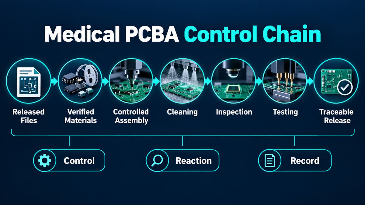
The process works as a controlled chain from engineering release to shipment. Each gate should define an input, an approved method, a result, a reaction to failure and a record.
1. Engineering Review and Production Baseline
The team reconciles schematic, Gerber/ODB++, drill data, BOM, CPL, assembly drawings, firmware and test documents. The control point is revision agreement: one obsolete BOM or placement file can create a board that looks correct but cannot pass functional verification. Buyers should request a released job package and a written list of resolved DFM/DFA questions.
2. Component Sourcing and Lot Traceability
Approved manufacturer part numbers, substitutions, date/lot data, moisture sensitivity and storage conditions are checked before kitting. The main risks are unauthorized substitution, mixed lots, counterfeit or damaged parts and expired exposure controls. Purchase records, incoming inspection results, substitution approvals and lot links provide the evidence.
3. Bare-Board and Material Verification
Bare PCBs are checked against the drawing and fabrication requirements before value is added. Surface condition, identification, critical dimensions and electrical-test evidence may be reviewed according to the agreed plan. A board with the wrong finish, revision or panel orientation can pass into assembly and cause solderability, fixture or traceability failures later.
4. Solder-Paste Printing and SPI
The stencil, paste condition, support tooling, print alignment and cleaning interval control the solder volume placed on each pad. Too little paste can form weak or open joints; excess or shifted deposits can bridge fine-pitch pads. Solder-paste inspection is useful when its limits and reaction plan are documented, not when it is treated as a decorative report.
5. Component Placement and Verification
Program revision, feeder setup, component identity, polarity, rotation and fiducial alignment are verified during placement. A correct part on the wrong rotation is still a functional failure. First-article checks, machine setup records and controlled feeder verification help prevent repeating a setup error across the lot.
6. Reflow, Through-Hole and Manual Soldering
The thermal process must suit the board, component population, solder system and joint geometry. Reflow profile drift can create incomplete wetting, voiding, bridging or component damage; manual operations add variability in heat input, flux use and handling. Record the approved recipe or work instruction, deviations and any special acceptance criteria for hidden or high-mass joints.
7. Cleaning and Contamination Control
Cleaning is a reliability decision, not a cosmetic step. Flux chemistry, component standoff, wash access, rinse quality, drying and subsequent coating all affect residue risk. Localized contamination beneath dense packages can escape a casual visual check. The buyer should define cleanliness requirements and ask how the process is verified for the actual assembly geometry.
8. Inspection, Rework Control and Test
Visual inspection, AOI, X-ray, electrical test, programming and functional test cover different failure modes. No single method proves total quality. Rework must preserve revision, workmanship and traceability and should trigger defined reinspection or retest. Release evidence should identify the unit/lot, test revision, result and disposition of any failure.
9. Final Release, Packaging and Shipment
Final release confirms that required records are complete and nonconformances are closed or formally accepted. Packaging must match ESD, moisture, mechanical and identification requirements. A passing board without a traceable label or with mixed release status can still be unusable for a controlled medical build.
Which Materials and Components Need Extra Control?
Materials need extra control when identity, storage, process compatibility or long-term availability can change assembly outcome. The BOM should distinguish approved manufacturer parts from distributor descriptions and should flag controlled substitutions, moisture-sensitive devices, programmed parts, batteries, sensors, connectors and components with polarity or special handling.
| Item | Assembly risk | Evidence to request |
| Bare PCB | Wrong revision, finish, construction or marking | Purchase specification, lot ID and agreed inspection/test record |
| Moisture-sensitive component | Package damage during reflow after excessive exposure | Packaging condition, exposure control and bake record when required |
| Substituted component | Electrical, mechanical, lifecycle or regulatory mismatch | Written approval tied to exact MPN and revision |
| Solder paste and flux | Process-window or residue incompatibility | Material identity, lot/expiry and controlled storage/use record |
| Programmed device | Correct hardware with wrong firmware | Firmware ID, programming result and checksum/version method |
How Should Traceability Be Defined?
Traceability should be defined from the failure question backward. If a field unit fails, the record system should let the owner identify the assembly revision, build lot or serial, critical component lots when required, process route, inspection/test results, rework history and shipment disposition.
More data is not automatically better. Decide which attributes are safety-, reliability- or compliance-relevant and how long records must be retained. A barcode has little value if it is not connected to usable job data.
What Inspection and Testing Are Appropriate?
The right inspection plan combines methods by defect coverage. SPI checks paste deposits; AOI checks visible placement and solder features; X-ray helps with hidden joints; electrical tests find defined connectivity or component faults; functional tests verify specified behavior under controlled conditions.
| Method | Strongest use | Coverage limit | Buyer question |
| SPI | Paste volume, position and print trends | Does not prove the final joint or circuit function | What limits and reaction rules stop the line? |
| AOI | Visible polarity, presence and solder features | Cannot fully see hidden BGA/LGA joints | How are programs validated and defects dispositioned? |
| X-ray | Hidden-joint alignment, bridges and void patterns | Interpretation depends on criteria and image quality | Which packages require X-ray and what is recorded? |
| ICT/flying probe | Defined opens, shorts and component measurements | Coverage depends on access and fixture/program design | What is the measured fault coverage? |
| Functional test | Specified behavior, interfaces and programmed operation | Only proves conditions included in the test procedure | Who owns limits, fixtures, software and golden units? |
For a deeper comparison, review ICT and functional-test coverage and define the test boundary before quotation.
What Are the Main Manufacturing Failure Risks?
The highest-cost failures are usually not a single visible solder defect; they are uncontrolled changes, undetected contamination, incomplete test coverage and records that cannot isolate affected units.
| Failure | Likely process source | Consequence | Prevention / evidence |
| Wrong component or firmware | Baseline, sourcing or programming control | Functional or validation failure | Approved MPN/version and recorded verification |
| Intermittent hidden joint | Paste, placement, reflow or package warpage | Escape from bench test and later field failure | Process trend, targeted X-ray and suitable stress/test plan |
| Residue-driven leakage/corrosion | Flux choice, wash access or drying | Time- and humidity-dependent failure | Assembly-specific cleaning validation and cleanliness evidence |
| Repeated rework damage | Uncontrolled repair cycles or heat input | Pad, laminate or component damage | Rework authorization, cycle record and required retest |
| Mixed release status | Identification and material flow failure | Unverified units enter shipment | Physical/electronic status segregation and final reconciliation |
How Does Design Affect Assembly Reliability?
Design determines whether the process can be controlled and inspected. Tight spacing, inaccessible test nodes, mismatched thermal masses, ambiguous polarity, low-standoff parts and coating/cleaning conflicts can create defects or blind spots even when the assembly line follows its instructions.
Before release, run DFM/DFA with the assembler and document critical characteristics. The PCBA quality-control methods should be selected around the design’s actual risk, not copied unchanged from another product.
How Are Prototype and Production Builds Connected?
A prototype proves learning; it does not automatically prove production repeatability. Before volume release, freeze the intended files, approved materials, process route, inspection programs, test revision and acceptance criteria. Record prototype deviations so an improvised wire, alternate part or manual tuning step does not silently become the production baseline.
A controlled low-volume PCB assembly process is useful for validating fixtures, instructions and test limits before scaling.
How Long Does Medical PCB Assembly Take?
Lead time cannot be estimated from board quantity alone. It depends on engineering-question closure, component availability, fixture/program readiness, first-article approval, special inspection, cleaning/coating, documentation and failure investigation. Ask the supplier to separate material lead time, engineering setup, assembly, inspection/test and approval holds rather than quoting one unexplained number.
How Do You Evaluate a Medical PCB Assembly Supplier?
Evaluate the supplier by the evidence it can produce for your defined risk. Confirm the applicable quality-system and certification status directly, but also review how it handles revisions, substitutions, traceability, process validation, inspection coverage, nonconformance, rework and changes.
- Send one controlled RFQ package and ask the supplier to identify contradictions.
- Request a sample traveler or traceability record with confidential data removed.
- Ask what defects SPI, AOI, X-ray and electrical tests can and cannot detect.
- Define who owns test fixtures, software, limits, maintenance and golden units.
- Ask how deviations and substitutions receive written approval.
- Confirm how failed and accepted units are physically segregated.
- Review the change-notification process before approving production.
What Should Be Included in the RFQ Package?
The RFQ should let the assembler quote the real control burden, not just placement count. Include Gerber/ODB++ and drill data, schematic, BOM with approved MPNs, CPL, assembly drawings, revision history, quantities, approved alternates, workmanship criteria, cleanliness/coating requirements, programming files, test specification, traceability fields, packaging and required release documents.
Frequently Asked Questions
Does medical PCB assembly require ISO 13485?
The required quality system depends on the customer’s contractual and regulatory framework. Verify the supplier’s current certificate scope and site directly; certification does not remove the need for project-specific controls and evidence.
Is AOI enough for a medical PCBA?
No single inspection method covers every defect. AOI is strong for visible features, while hidden joints and functional behavior may require X-ray, electrical or functional testing according to risk.
What files are needed for quotation?
Send fabrication data, BOM, CPL, assembly drawings, quantities and acceptance requirements. Add schematic, firmware and test documents when programming or functional verification is required.
How should component substitutions be handled?
Use an approved-alternate process tied to the exact manufacturer part number, affected revision and technical evaluation. Do not accept an unrecorded distributor-level equivalent for a controlled build.
Why is PCBA cleanliness important?
Residue and particles can contribute to leakage, corrosion, coating adhesion problems or time-dependent failures. The cleaning and verification method must match the flux, geometry and service risk.
What should a first-article report include?
Its scope should match the project, but typically links revision, materials, setup verification, inspection/test results and deviations to a defined unit or lot. Agree the format before production.
Can a prototype process be used for mass production?
Only after temporary substitutions, manual adjustments, test shortcuts and undocumented rework are resolved into a controlled production baseline. A working prototype alone does not prove repeatability.
Who is responsible for medical-device approval?
The legal manufacturer/device owner retains responsibility for device classification, risk management, validation and regulatory approval. The PCBA supplier provides controlled manufacturing and agreed evidence within its contracted scope.
Request an Engineering and Assembly Review
For a medical electronics project, send Thindry the released PCB data, BOM, CPL, assembly drawings, quantities, traceability requirements and test plan. Request a review of file consistency, material controls, inspection coverage, cleaning/coating compatibility and release documentation before committing the build. Contact [email protected] with the project package for evaluation and quotation.



0 Comments