




If you want to know How to Test a PCB with a Multimeter, the best approach is not to guess, replace parts at random, or start probing without a plan. A PCB failure usually falls into one of three groups: a short circuit, an open circuit, or a failed component. Once you know which one you are dealing with, the repair gets much easier.
This guide focuses on practical troubleshooting. It starts with safety and preparation, then moves through a clear testing order, probe placement, and the readings that matter most. The goal is simple: help you narrow down the fault as quickly as possible without making the problem worse.
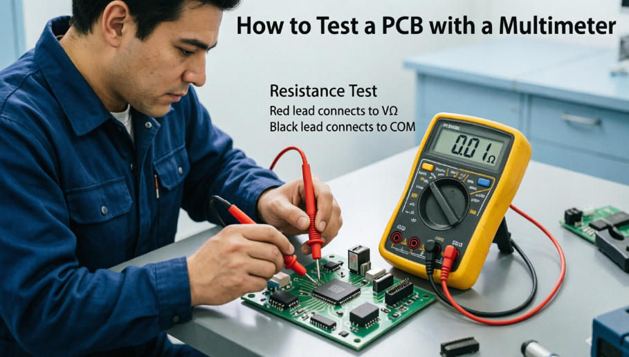
What Are You Trying to Find on a Dead PCB: Short, Open, or Failed Component?
When a PCB stops working, the problem usually sits in one of three buckets.
A short circuit means two points that should not be connected are now connected too easily. On a board, that may show up as a power rail pulled toward ground, a fuse that keeps blowing, or a part that gets hot almost immediately.
An open circuit means a path that should be connected is broken. That could be a cracked trace, a bad solder joint, a broken connector pin, or a component that has failed internally.
A failed component is often what people suspect first, but it is not always the easiest thing to prove. A resistor can drift high or go open. A diode can short. A capacitor can short or leak. A regulator can look normal from the outside and still be dead inside.
When you are learning How to Test a PCB with a Multimeter, the real skill is not jumping to the first conclusion. The real skill is figuring out which of these three failure types is most likely before you start replacing parts.
How to Test a PCB with a Multimeter: Start with Safety and a Clear Order
If you want fast answers, test the board in a logical order. Do not begin by checking random parts just because they are easy to reach.
- Inspect the board visually.
- Check for shorts with the power off.
- Test continuity through traces, fuses, connectors, and obvious signal paths.
- Test the parts closest to the fault area.
- Only move to powered testing after the board is not obviously shorted.
This order works because each step gives you more information than the last one. A burned spot can point you toward the failed area. A short between power and ground can explain why the board never starts. An open trace can explain why only one section is dead. By the time you test individual components, you already know where to look.
Before you touch the board
Power the board off and disconnect it from the supply before any resistance or continuity testing.
If the board contains large capacitors, discharge them safely first. Some boards can hold charge even after unplugging, especially power supplies, motor control boards, and audio equipment.
A few habits make troubleshooting safer and easier:
- Use ESD-safe handling for sensitive boards.
- Inspect the board under strong light.
- Look for burned parts, corrosion, cracked solder joints, and lifted pads.
- Keep probe tips clean and sharp.
- Use fine-tip probes on dense boards or small pads.
When you are figuring out How to Test a PCB with a Multimeter, setup matters almost as much as the measurement itself. A clean board, a safe board, and a clear test plan save a lot of time.
Read the Board Before You Measure Anything
Before you start probing, spend a minute reading the board like a map.
Find the power input, the ground points, the fuse, the regulator, and the area that looks suspicious. If you have a schematic or even a photo of a known-good board, that helps a lot. You do not need to understand every trace. You only need to know where power comes in and where it is supposed to go.
Look closely for:
- Burn marks or dark spots
- Cracked solder joints
- Corrosion from moisture or battery leakage
- Lifted pads
- Broken connector pins
- Bulged or damaged capacitors
- Parts that look hotter, duller, or different from the rest
This quick scan often tells you where to begin. Many board failures are not hidden. They are just easy to miss if you rush straight into measuring.
How to Test PCB Traces and Connectors for Continuity
Continuity testing is one of the fastest ways to find a broken path on a board.
Set your multimeter to continuity mode. This is usually the setting with the beep symbol.
Use continuity mode on a powered-off board only.
Where to place the probes
Put one probe on one end of the trace, connector pin, fuse, or solder joint. Put the other probe on the point you want to confirm is connected.
Examples:
- One end of a trace to the other end
- Connector pin to via
- Fuse input to fuse output
- Ground point to another ground point
What a good reading looks like
A good connection usually gives:
- a beep, or
- a very low resistance reading
An open path usually gives:
- no beep, or
OL, depending on the meter and range
What can confuse the result
In-circuit continuity tests can be misleading because the path may connect through other components. A beep does not always mean the exact trace you expected is intact. It only means there is a conductive route between the probes.
That is why continuity is best used as a first check, not the final answer.
How to Test for a Short Circuit on a PCB
If the board blows a fuse, draws too much current, or fails instantly when powered, a short circuit is one of the first things to check.
Set the meter to ohms mode or continuity mode, depending on what your meter handles best for low-resistance checks.
Then measure between the main power rail and ground.
How to probe
- Put the black probe on ground.
- Put the red probe on the power rail or the point you suspect is shorted.
If the reading is very close to zero ohms, or the continuity beep is immediate and strong, that is a warning sign. It does not always prove a hard short by itself, but it does tell you the rail needs more attention.
What to look for
- A very low reading between power and ground can point to a shorted capacitor, IC, TVS diode, or solder bridge.
- A rail that starts low and then rises a little may be charging through the meter and may not be a true short.
- If possible, compare with a known-good board or a similar rail on the same board.
If you find a short, do not jump straight to replacing the biggest chip on the board. Narrow the area first. Check nearby capacitors, protection diodes, power ICs, and solder bridges. Many shorts come from small parts, not the main controller.
How to Test Resistors on a PCB: Meter Setting, Probe Placement, and Normal Readings
Resistors are a good place to start because they are simple and usually easy to measure.
Use ohms mode.
Probe placement
Put one probe on each end of the resistor.
- Red probe on one side
- Black probe on the other side
For most resistors, probe direction does not matter.
What normal looks like
If the resistor is isolated, the reading should be close to the marked value.
Examples:
- A
1 kΩresistor may read near1.0 kΩ - A
10 kΩresistor may read near10 kΩ - A
100 Ωresistor may read near100 Ω
Small differences are normal. Resistors have tolerance, and the circuit around them can affect the reading.
What looks abnormal
OLor very high resistance may suggest an open resistor- A reading much lower than expected may mean the resistor is being measured in-circuit with parallel paths around it
- A reading near
0 Ωmay mean the resistor is shorted, but it can also mean another part of the circuit is affecting the result
A resistor on the board is not always easy to judge in place. If the reading does not make sense, lift one end and test it again out of circuit. That simple step often turns a confusing result into a clear one.
How to Test Capacitors on a PCB: Meter Setting, Polarity, and Fault Signs
Capacitors need a little more care, especially electrolytic capacitors.
If your meter has a capacitance mode, use that first. If it does not, you can still learn a lot from resistance mode, but the result will be less exact.
Before testing
Power the board off and discharge the capacitor first.
That matters because a charged capacitor can give you a false reading and can also be unsafe to probe.
Probe placement
For non-polarized capacitors, direction usually does not matter.
For polarized electrolytic capacitors:
- red probe to the positive side
- black probe to the negative side
That is the clearest way to test them when the board layout allows it.
What a normal reading looks like
On a meter with capacitance mode, the value should be reasonably close to the rated value, allowing for tolerance.
In ohms mode, a healthy capacitor often shows a brief low reading that rises as the capacitor charges from the meter.
That rising behavior is useful. It suggests the capacitor is not shorted.
What looks abnormal
- A steady near-zero resistance reading may indicate a shorted capacitor
OLwhere you expect a measurable value may suggest an open part or a bad connection- A capacitance value far below the rating can point to degradation
- A capacitor that behaves very differently from similar parts on the board deserves attention
A practical example
If you test a decoupling capacitor on a power rail and the meter shows almost direct continuity to ground, do not assume the capacitor is the only problem. It may be the part that is shorted, but it may also be showing you a shorted rail somewhere else on the board.
That is one of the most important habits when learning How to Test a PCB with a Multimeter: do not stop at the first suspicious reading. Ask what the board is trying to tell you.
How to Tell Normal Readings from Abnormal Readings
A good reading is not just a number. It is a number that makes sense in context.
Here is a practical way to think about it:
- Continuity beep usually means the path is connected.
OLusually means open circuit, but in-circuit measurements can be misleading.- Very low resistance between power and ground often points to a short.
- A resistor lower than expected may be affected by parallel parts on the board.
- A capacitor that behaves like a short and never recovers is suspicious.
- A powered rail with no voltage points to an upstream supply, fuse, regulator, or trace problem.
If you are comparing readings, use the same probe points each time. Small differences in probe placement can change the reading enough to confuse the diagnosis.
Unpowered Testing vs Powered Testing: When to Use Each Method
One of the most useful parts of How to Test a PCB with a Multimeter is knowing when to leave the board off and when to power it on.
Use unpowered testing for
- Continuity checks
- Resistance checks
- Short-to-ground checks
- Diode and capacitor checks in many cases
Use powered testing for
- Checking whether the board receives the correct supply voltage
- Measuring voltage on power rails
- Confirming whether a regulator is working
- Seeing whether a signal or rail collapses under power
When the board is powered, black probe placement usually matters more. In most cases, put the black probe on a solid ground point and use the red probe to check the voltage at the point you care about.
Powered testing is useful, but it should come after the board has passed the basic unpowered checks. If you power a board that already has a hard short, you can damage it further.
A simple rule
If you are not sure whether the board is shorted, test it unpowered first. If the board looks safe enough to power, then move to voltage checks.
How to Test Diodes on a PCB
Diodes are small parts, but they can cause big problems when they fail.
Use diode mode on the meter.
Probe placement
For a normal diode test:
- red probe on the anode
- black probe on the cathode
A healthy diode usually shows a forward voltage drop in one direction and no conduction in the other direction.
What to expect
- Forward direction: a typical reading around
0.2 Vto0.8 V, depending on diode type - Reverse direction:
OLor no conduction
If a diode reads close to zero in both directions, it may be shorted. If it reads OL in both directions, it may be open. In-circuit readings can be confusing here too, so if the result is not clear, lift one side and test again.
What Multimeter Is Best for PCB Repair?
If you repair PCBs regularly, the right meter makes a real difference.
You do not need the most expensive meter on the shelf, but you do want one that makes small faults easier to find.
Useful features for PCB work
- Fast continuity response
- Clear resistance readings at low ohms
- Diode test mode
- Capacitance mode
- Stable auto-ranging or reliable manual range control
- Fine-tip probes or the option to use them
For dense boards, probe quality matters almost as much as the meter itself. Fine tips make it easier to land on small pads without slipping. Stable leads also help when you are checking the same point over and over.
If you mostly work on PCB repair, a good general-purpose multimeter with solid continuity response is often more useful than a meter with a lot of features you will never use.
Quick Troubleshooting Examples
Here are a few simple examples that show how to apply How to Test a PCB with a Multimeter in real troubleshooting work.
Example 1: The board does not power on
Start by checking the input fuse, connector, and power rail continuity with the board off. If the fuse is open, check whether something downstream caused it to fail. If the fuse is good but the power rail is shorted to ground, move toward the short before applying power again.
Example 2: A resistor in the circuit reads too low
Measure the resistor in ohms mode with the board off. If the reading is lower than expected, look for parallel paths through the rest of the circuit. If the reading still looks wrong, lift one end and test it again out of circuit.
Example 3: A capacitor looks shorted
Check the capacitor with the board off and discharged. If it reads near zero ohms and never starts to rise, that is a strong warning sign. If the same rail is also near zero to ground, the capacitor may be the part that failed, or it may simply be showing you a short elsewhere on the rail.
Example 4: A connector pin has no continuity
Test from the pin to the next point on the trace. If there is no beep, inspect the solder joint, the pad, and the trace itself. A broken connector pin or cracked joint is common and easy to miss visually.
Common Mistakes to Avoid
A few mistakes come up again and again in PCB troubleshooting:
- Testing a live board in continuity mode
- Assuming one reading proves the whole fault
- Ignoring parallel paths in the circuit
- Skipping the visual inspection
- Replacing parts before checking for shorts or opens
- Using thick probe tips on tiny pads and slipping across nearby pins
If you avoid those mistakes, your results will be far more reliable.
Final Check: What You Should Know Before Replacing Parts
Before you replace anything, make sure you can answer these questions:
- Is the board shorted, open, or both?
- Where exactly is the fault area?
- Is the reading still valid when the part is tested out of circuit?
- Did you compare the reading with a similar section or a known-good board?
- Have you checked the supply path before blaming the component?
That is the practical side of How to Test a PCB with a Multimeter. It is less about collecting numbers and more about using the right order, the right probe placement, and the right interpretation to make the board tell you what is wrong.
FAQ
Can I test a PCB without removing components?
Yes, in many cases you can. Continuity, resistance, diode, and voltage checks can all be done with parts still on the board. Just remember that in-circuit readings can be influenced by other components.
What setting should I use first?
For an unpowered board, start with continuity and ohms mode. For a powered board, use voltage mode. If you are checking a diode, use diode mode. If your meter supports capacitance mode, that can help with capacitor checks.
Why does continuity beep even though the board still fails?
Because continuity only tells you there is a conductive path. It does not prove that the path is correct, stable, or able to carry current the way it should under real operating conditions.
Should I test the board powered or unpowered?
Start unpowered for shorts, opens, and basic component checks. Move to powered testing only after the board looks safe enough to energize.
What if the power rail reads normal but the board still does not work?
Then the problem may be farther downstream. The rail may be present, but a regulator, signal path, clock, connector, or load section may still be failing.
When should I lift one end of a component?
When the in-circuit reading is unclear and you need to know whether the part itself is bad or the surrounding circuit is affecting the measurement.
Conclusion
If you are learning How to Test a PCB with a Multimeter, the key is to work in the right order: start with safety, inspect the board, check for shorts, test continuity, measure suspect components, and only then move to powered voltage checks.
Once you get used to that process, PCB troubleshooting becomes much less random. Instead of guessing, you can narrow the fault down to a short, an open path, or a failed component with much more confidence.



0 Comments