




I remember the first time I held a rigid-flex PCB in my hands. It was about twelve years ago, and I was working on a compact sensor module for a medical client. The engineer on the other end of the phone kept insisting that no single rigid board could fit inside the enclosure and still connect to a secondary sensor mounted on a hinged arm. I half-expected a mess of cables and connectors when the prototype arrived. Instead, what showed up was a single, elegant board, half rigid, half flexible, folding neatly into a space that should have been physically impossible to populate with electronics.
That experience stuck with me. It also reminded me that rigid-flex technology, despite being around since the 1960s (the Minuteman missile program, if you are curious), is still widely misunderstood. Engineers who have spent their careers designing standard rigid boards often do not realize what they are leaving on the table. And engineers who have used rigid-flex sometimes over-spec it for applications where a simpler solution would do just fine.
This guide is an attempt to cut through the noise. We will cover what a rigid-flex PCB actually is, how it is built, where it shines, where it falls short, and perhaps most importantly, how to know whether your project truly needs one.
What Is a Rigid-Flex PCB?
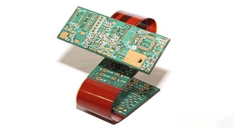
A rigid-flex PCB is a single printed circuit board that combines rigid board sections and flexible circuit sections into one continuous, laminated structure. Unlike a rigid board connected to a separate flex cable through a connector, everything is manufactured as a unified piece. There are no plugs, no solder joints between sub-assemblies, and no extra failure points. The rigid sections carry most of the components and traces, while the flex sections allow the board to bend, fold, or wrap into three-dimensional shapes.
Think of it this way: if a standard PCB is a flat sheet of paper and a flex PCB is a sheet of tracing paper, a rigid-flex PCB is a piece of cardstock with tracing paper seamlessly bonded into certain zones. The stiff parts hold their shape. The thin parts bend exactly where you need them to.
How a Rigid-Flex PCB Is Built — Structure and Layers
Understanding the internal structure of a rigid-flex board helps explain both its advantages and its manufacturing complexity.
At the core, you have rigid zones and flex zones within the same board:
- Rigid zones use standard FR-4 or high-Tg laminate cores, copper layers, and solder mask — essentially a normal PCB. Components get mounted here, and most of the signal routing lives in these sections.
- Flex zones use polyimide (commonly known by the trade name Kapton) as the base dielectric, with rolled or electrodeposited copper traces laminated onto it. These zones are thin — typically 0.1 to 0.3 mm total thickness — and designed to bend.
- Bonding layers connect everything together. During lamination, the rigid and flex sub-assemblies are pressed under heat and pressure with adhesive or adhesiveless prepreg systems to form one monolithic structure.
The number of layers varies. Simple rigid-flex boards might have 4 to 6 layers in the rigid sections and 1 to 2 layers in the flex sections. Complex designs for aerospace or medical applications can go up to 12 or even 14 layers in the rigid zones, with multiple independent flex tails branching off.
One design detail that trips up newcomers: the flex zones often have a different layer count than the rigid zones. For example, you might have a 6-layer rigid section with only 2-layer flex extensions. Transitions between these different layer counts happen at the rigid-flex interface, which is the most mechanically sensitive part of the entire board.
Key Standards: IPC-2223
The primary industry guideline for flex and rigid-flex PCB design is IPC-2223 (Sectional Design Standard for Flexible Printed Boards). It covers material selection, bend radius rules, copper weight recommendations, coverlay requirements, and reliability testing. If you’re designing a rigid-flex board for the first time, reading through IPC-2223 Section E (which specifically addresses rigid-flex constructions) will save you a significant amount of grief during manufacturing review.
Rigid-Flex PCB vs. Other PCB Types
This is where a lot of engineers get stuck. The decision between rigid, flex, rigid-flex, and hybrid assemblies (rigid boards connected by discrete FPCs) isn’t always obvious. Here’s how the options compare.
Rigid-Flex PCB vs. Rigid PCB
| Factor | Rigid PCB | Rigid-Flex PCB |
|---|---|---|
| Structure | Single flat board, all-rigid | Combined rigid + flex zones in one board |
| Flexibility | None | Flex zones can bend to fit 3D spaces |
| Space efficiency | Limited to 2D layout | Enables 3D packaging and tight enclosures |
| Reliability | Depends on connectors/cables between boards | Fewer interconnection points = fewer failure modes |
| Signal integrity | Good, but degrades at cable/connector transitions | Better — continuous copper paths without connector impedance mismatches |
| Assembly | Standard SMT process | Similar for rigid zones; flex zones may need special fixturing |
| Cost | Lower | 1.5x to 3x higher depending on complexity |
| Design complexity | Straightforward | Significantly more involved |
Bottom line: If your design fits comfortably on a single flat board and your enclosure is a simple box, stick with rigid. The moment you need to fold a circuit around a corner, squeeze into an irregularly shaped housing, or eliminate a cable harness, rigid-flex enters the conversation.
Rigid-Flex PCB vs. Flexible PCB (FPC)
A pure flexible PCB is thin, lightweight, and bendable — but it can’t independently hold components the way a rigid board does. Without structural support, FPCs need a stiffener (typically a thin FR-4 or stainless steel plate) behind component areas, and they usually require an additional support structure or housing to maintain their shape in the final product.
Rigid-flex solves this by giving you built-in rigid zones that provide mechanical support, thermal dissipation paths, and standard PCB-level component density — all integrated into the same board. You don’t need to design separate stiffeners or worry about aligning them during assembly.
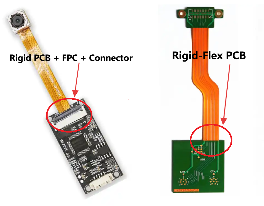
Rigid-Flex PCB vs. Rigid PCB + Cable/FPC + Connector
This is the comparison that matters most for engineers evaluating whether to “go rigid-flex” or just wire things together with a FPC and a ZIF connector. Here’s the honest breakdown:
The rigid + cable + connector approach is cheaper to manufacture, easier to redesign on the fly, and simpler to troubleshoot when something goes wrong. For prototypes and low-to-medium volume products where size isn’t critical, it’s often the pragmatic choice.
But every connector is a potential point of failure. Every solder joint between a cable and a board is a site where vibration, thermal cycling, or mechanical shock can eventually cause a crack. Every FPC-to-board interface introduces impedance discontinuity that matters at high frequencies.
When your product will see thousands of bend cycles (a foldable phone, for instance), must survive harsh vibration (a drone in flight), operates at frequencies above a few GHz (5G antenna modules), or simply has no room for connectors (an implantable medical device), the integrated approach of rigid-flex eliminates these concerns entirely. You pay more upfront in design and manufacturing, but you gain a fundamentally more robust product.
Advantages of Rigid-Flex PCBs
Space savings and 3D packaging. This is the number one reason engineers reach for rigid-flex. A board that folds around a battery, wraps along a curved housing wall, or tucks into an L-shaped cavity lets you use every cubic millimeter of available space. Consumer electronics designers live and die by this. The difference between fitting a 300 mAh battery and a 400 mAh battery can come down to whether the PCB folds once or stays flat.
Higher reliability. Fewer connectors, fewer solder joints, fewer cables. In a product that will be dropped, shaken, flexed, or subjected to temperature extremes, every interconnection you eliminate is a win. Rigid-flex boards routinely pass 200,000 or more bend cycle tests when designed properly, far outlasting any ZIF connector or soldered cable joint.
Better signal integrity. When a high-speed signal travels from a rigid section through a flex zone and back into a rigid section, it stays on a continuous copper trace with controlled impedance. There is no connector with its associated capacitance, no cable with its unpredictable geometry. For differential pairs running at several Gbps, this matters. You can tune the impedance of the flex zone just as you would the rigid zone, keeping the signal clean throughout.
Reduced weight. Eliminating cables, connectors, and mounting hardware adds up. In aerospace and wearable applications, where every gram counts, rigid-flex boards can shave meaningful weight compared to equivalent wired assemblies.
Simplified assembly. Instead of soldering cables between boards and routing them through the enclosure, you fold the rigid-flex board into shape and mount it as a single unit. In high-volume manufacturing, this can reduce assembly time and labor costs significantly, partially offsetting the higher per-board PCB cost.
Improved thermal management. The rigid zones provide solid copper planes for heat spreading, while the flex zones, though thinner, still offer a conductive path. Compared to an FPC dangling in free air with no thermal mass, a rigid-flex board handles heat dissipation much better.
Disadvantages and Limitations of Rigid-Flex PCBs
Higher cost. There is no getting around this. A rigid-flex board typically costs 1.5 to 3 times more than an equivalent rigid board, depending on the number of flex zones, the layer count, and the complexity of the lamination. For very simple designs, the cost difference can be even larger on a percentage basis because there are fixed costs associated with the flex material and the specialized manufacturing steps that do not scale down well for small prototypes.
Longer lead times. Standard rigid PCBs can sometimes be fabricated in 24 to 48 hours for expedited orders. Rigid-flex boards almost never can. The lamination cycle, the precision alignment required between rigid and flex layers, and the additional inspection steps mean you are generally looking at two to four weeks for production, even at experienced fabricators. Prototypes may take longer if the design involves unusual stackups.
More complex design process. Designing a rigid-flex board is not just designing a rigid board and adding some bends. You need to plan bend radii, route traces through flex zones following specific guidelines, manage impedance transitions between rigid and flex sections, and coordinate with your fabricator early to confirm that your stackup is actually manufacturable. Mistakes in the design phase are expensive to fix after fabrication.
Repairability challenges. When a rigid board fails, you can often rework a component, reflow a joint, or patch a trace. When a rigid-flex board fails in the flex zone, repair is usually not practical. The polyimide substrate and coverlay are difficult to access and nearly impossible to restore to original specifications once damaged. This means you need to get the design right the first time.
Limited supplier capability. Not every PCB fabricator can produce rigid-flex boards. Even among those that claim the capability, there is a wide range in quality and yield. You will need to vet your supplier carefully, particularly for applications that demand high reliability or tight tolerances.
When Should You Use a Rigid-Flex PCB?
This is the question that matters most, and the answer depends entirely on your application. Here is a breakdown by industry.
Consumer Electronics
Smartphones, smartwatches, TWS earbuds, and VR headsets are the poster children for rigid-flex technology. Inside a modern smartwatch, you might find a rigid-flex board that folds around the battery, connecting a main processing board on one side to a sensor board and display driver on the other. The entire assembly fits inside a housing smaller than a matchbox.
Foldable phones take this further. The hinge mechanism requires a flex zone that bends every time the user opens and closes the device. Samsung, Huawei, and other manufacturers use multi-layer rigid-flex boards with specially engineered bend zones rated for hundreds of thousands of cycles.
If you are designing a compact consumer device where every millimeter matters and the product will be handled roughly by end users, rigid-flex is likely the right approach.
Medical Devices
Medical electronics have some of the most demanding requirements in the industry. Implantable devices like cardiac pacemakers and cochlear implants use rigid-flex boards to conform to the shape of the human body. Diagnostic equipment like endoscopes need PCBs that can navigate tight, curved spaces inside the human anatomy.
Reliability is non-negotiable in this field. A connector coming loose inside a patient-worn device is not just an inconvenience; it is a safety hazard. Rigid-flex boards, with their monolithic construction, eliminate that risk. They also tend to perform well under the repeated sterilization cycles that medical devices endure.
Aerospace and Defense
Satellites, avionics, radar systems, and military communication equipment all benefit from rigid-flex technology. The combination of extreme weight constraints, harsh vibration environments, and the need for absolute reliability makes rigid-flex an obvious fit.
A satellite in orbit cannot be serviced. If a cable comes loose during launch vibration, that satellite is dead. Rigid-flex boards, properly designed and tested, are built to survive those forces without relying on mechanical interconnects that could fail.
The defense sector also values rigid-flex for its resistance to tampering. A monolithic board is harder to reverse-engineer than a multi-board assembly connected by cables.
Automotive
Modern vehicles are packed with electronics, and the trend toward autonomous driving is accelerating this. ADAS camera modules, radar units, LiDAR assemblies, and in-vehicle infotainment systems all present packaging challenges where rigid-flex shines.
Under-hood applications pose particular challenges. Engine bay temperatures can exceed 125 degrees Celsius for extended periods, and vibration from the engine and road is constant. Rigid-flex boards designed with high-Tg materials and reinforced bend zones handle these conditions far better than cable-connected assemblies.
Industrial and Robotics
Robotic joints, articulated arms, and sensor arrays mounted on moving parts are natural applications for rigid-flex. The flex zone acts as an integrated hinge, eliminating external wiring that would fatigue and break under repeated motion.
Factory automation equipment also benefits. Sensor modules mounted on conveyor systems, pick-and-place machines, and automated inspection equipment often need to bend or conform to non-planar surfaces while maintaining reliable signal paths.
Telecommunications and 5G
5G infrastructure, particularly massive MIMO antenna arrays and small cell deployments, relies heavily on rigid-flex technology. The antenna elements need precise spacing and orientation, and the RF signal paths between the antenna and the beamforming electronics must maintain tight impedance control.
Rigid-flex boards let designers route high-frequency signals from a planar antenna array through a flex zone to a compact electronics module mounted behind the antenna, without the signal degradation that comes from connector transitions and cable runs.
When Should You Not Use a Rigid-Flex PCB?
Knowing when not to use rigid-flex is just as important as knowing when to use it.
If your product is housed in a simple rectangular enclosure with plenty of internal space, you probably do not need rigid-flex. A standard rigid board with a conventional cable harness will be cheaper, faster to produce, and easier to service.
If your production volume is very high and cost per unit is a critical competitive factor, the rigid-flex premium may be hard to justify unless the performance benefits are truly necessary. In high-volume consumer products, even a one-dollar cost difference per unit can add up to millions over a product lifecycle.
If your design is still in the early prototyping phase and you expect significant layout changes, rigid-flex is a risky investment. The lead times and costs associated with design iterations are much higher than for standard rigid boards. Get your design stable on rigid boards first, then convert to rigid-flex once you are confident in the layout.
If the bend requirement is simple and infrequent, a rigid board connected by an FPC with a connector may be perfectly adequate. Not every fold justifies the full rigid-flex treatment.
How to Design a Rigid-Flex PCB
Designing a rigid-flex board successfully requires attention to several details that do not come up in standard rigid PCB design. Here are the most important guidelines.
Bend Radius
This is the single most critical design parameter for the flex zones. Bend too tightly, and the copper traces crack. Bend too far outside the minimum, and you are wasting the flex capability you paid for.
As a general rule, the minimum bend radius for a single-layer flex zone is at least 6 times the total thickness of the flex stackup. For multilayer flex zones, the minimum increases to 10 times the thickness or more. These are static bend minimums. For dynamic bending, where the board will be flexed repeatedly, you need to increase the radius further, typically to 15 to 20 times the thickness.
Always confirm the minimum bend radius with your fabricator. The specific materials and construction methods they use affect the numbers, and their data will be more accurate than any general guideline.
Bend Zone Design
The bend zone is the flex area that actually moves. Design rules for this zone are strict.
Do not place vias, component pads, or plated holes in the bend zone. These features create stress concentrators in the copper and the substrate, and they will crack under repeated bending. Keep the bend zone clean: copper traces and nothing else.
Route traces perpendicular to the bend axis. Traces running parallel to the bend line experience the maximum strain during flexing. Traces running perpendicular experience almost none. If you must route a trace at an angle, keep it as close to perpendicular as possible and use teardrop pads at the transition points where traces enter and exit the bend zone.
Use rounded corners on all traces in the flex zone. Sharp 90-degree and 45-degree bends in copper traces create stress points. Gentle curves distribute the stress more evenly.
Layer Stackup Planning
Work with your fabricator from the start to define the stackup. Rigid-flex stackups are more constrained than rigid-only stackups because the flex layers must be compatible with the lamination process and the rigid layers must accommodate the transition at the interface.
Common configurations include 2-layer flex with 4-layer rigid, 4-layer flex with 6-layer rigid, and 6-layer flex with 8-layer rigid. Going beyond these ranges is possible but increases cost and complexity significantly.
The transition zone between rigid and flex is where most failures occur. Plan this area carefully. The copper traces that cross from rigid to flex should do so gradually, with no abrupt changes in width or direction. Staggering the transitions across different layers, rather than stacking them all in one location, distributes mechanical stress more evenly.
Material Selection
Polyimide is the standard flex substrate material for good reason. It has excellent thermal stability, good mechanical flexibility, and well-characterized electrical properties. However, there are different grades of polyimide, and not all of them are created equal.
Standard polyimide with adhesive bonding works for most applications. Adhesiveless polyimide (where the copper is bonded directly to the polyimide film without an intermediate adhesive layer) offers better flex life, lower thickness, and improved impedance control, but at a higher cost.
For the rigid sections, standard FR-4 is fine for most designs. If your application involves high temperatures, consider high-Tg FR-4 or polyimide-based rigid laminates.
Common Design Mistakes
Overdesigning the number of layers is the most expensive mistake. Every additional layer in the flex zone increases material cost, lamination complexity, and reduces bend life. Before adding a layer, ask yourself whether the routing problem it solves can be resolved by rerouting on existing layers.
Ignoring the bend cycle requirement is the second most common mistake. If the product requires dynamic bending, you must design for it from the start. You cannot take a design optimized for static installation and expect it to survive repeated flexing.
Skipping the design review with your fabricator is the third. Rigid-flex designs that look perfect in your EDA tool can turn out to be unmanufacturable or prohibitively expensive when the fabricator evaluates them. A 30-minute conversation before you release the gerber files can save weeks of delay and thousands of dollars.
The Rigid-Flex Manufacturing Process
A brief overview of how rigid-flex boards are made helps explain both the cost and the lead time.
The process begins with preparing the individual rigid and flex sub-assemblies. The flex layers are fabricated first, with copper patterning on polyimide film, followed by coverlay lamination (the flex equivalent of solder mask). The rigid layers are processed similarly to standard PCB cores.
The critical step is lamination, where the rigid and flex sub-assemblies are stacked with prepreg bonding layers and pressed together under heat and pressure. Alignment is critical. The rigid layers and flex layers must be registered within very tight tolerances, typically better than 75 microns, across the entire panel.
After lamination, the board goes through drilling, copper plating, outer layer patterning, solder mask application, and surface finish, similar to a standard rigid PCB. The difference is that the fabricator must now handle a board with zones of very different thickness and flexibility, which requires special fixturing and handling throughout the process.
Inspection is more thorough as well. Cross-sectioning of sample boards from each panel, bend testing of test coupons, and 100 percent X-ray inspection of layer-to-layer alignment are all standard practice at reputable rigid-flex fabricators.
Cost Factors: How Much Does a Rigid-Flex PCB Cost?
The cost of a rigid-flex PCB depends on several variables, and understanding them helps you make informed design decisions.
Layer count in the rigid and flex sections is the primary driver. Each additional layer adds material and processing steps. Flex layers are more expensive per layer than rigid layers because polyimide material costs more than FR-4 and the lamination requirements are stricter.
The number of flex zones matters. A board with one flex tail is much cheaper to manufacture than a board with three flex tails radiating from a central rigid hub, even if the total copper area is similar, because each flex zone requires its own lamination and alignment.
Copper weight, surface finish, minimum trace width and spacing, and hole sizes all affect cost in the same way they do for standard rigid boards, but the penalties tend to be steeper for rigid-flex because the fabricator has less margin for error.
Delivery schedule has an outsized impact on rigid-flex pricing. Standard two to three week lead times are the baseline. Expedited orders carry significant premiums because they disrupt the fabricator’s production schedule and reduce yield.
As a rough reference, expect a well-designed 4-layer rigid with 2-layer flex board to cost roughly twice as much as an equivalent 4-layer rigid board. More complex configurations with multiple flex zones and higher layer counts can push the multiplier to three or beyond.
Frequently Asked Questions
What is a rigid-flex PCB?
A rigid-flex PCB is a single circuit board that integrates rigid board sections and flexible circuit sections into one laminated assembly. It allows the board to bend or fold into three-dimensional configurations while supporting surface-mount components on the rigid zones.
What is the difference between a rigid-flex PCB and a flex PCB?
A flex PCB is entirely flexible and typically needs a stiffener or support structure to hold components. A rigid-flex PCB has built-in rigid zones that provide mechanical support, thermal paths, and full component density without requiring external stiffeners.
How much more does rigid-flex cost compared to standard rigid PCBs?
Costs vary by design, but expect rigid-flex to be roughly 1.5 to 3 times the cost of an equivalent rigid board. The exact multiplier depends on layer count, number of flex zones, and manufacturing complexity.
Can rigid-flex PCBs withstand high temperatures?
Yes, when built with appropriate materials. High-Tg FR-4 in the rigid zones and polyimide in the flex zones provide good thermal performance. Polyimide is stable at continuous operating temperatures above 200 degrees Celsius.
How many bend cycles can a rigid-flex PCB endure?
This depends on the bend radius, copper weight, polyimide grade, and construction method. Well-designed boards with adhesiveless polyimide and appropriate bend radii can exceed 200,000 dynamic bend cycles. Static-bend applications, where the board is folded once during assembly, have essentially unlimited life.
What industries use rigid-flex PCBs the most?
Consumer electronics, medical devices, aerospace and defense, automotive, industrial automation, and telecommunications are the primary markets. Consumer electronics accounts for the largest volume by unit count, while aerospace and defense tend to have the highest per-unit value.
Is rigid-flex PCB design more difficult than standard rigid PCB design?
Yes. You need to account for bend radii, flex zone routing rules, layer transitions, impedance control across different substrates, and coordinate with your fabricator early in the process. Engineers who are new to rigid-flex should expect a learning curve.
What is the minimum bend radius for a rigid-flex PCB?
For static bending (folded once during assembly), the minimum is typically 6 to 10 times the flex section thickness. For dynamic bending (repeated flexing during use), increase this to 15 to 20 times the thickness. Always confirm with your fabricator.
Final Thoughts
Rigid-flex technology isn’t a magic bullet, and it’s not always the right answer. But for the right application — where space is at a premium, reliability is non-negotiable, and the product demands a three-dimensional electronic assembly — it solves problems that no other PCB technology can.
The decision to use rigid-flex should be driven by your product’s mechanical constraints, environmental demands, and total system cost — not by the appeal of a fancy manufacturing process. When those factors align, though, rigid-flex delivers a level of integration and reliability that’s genuinely difficult to achieve any other way.
If you’re at the stage where you’re evaluating rigid-flex for an upcoming project, start the conversation with your manufacturer early. A twenty-minute stackup discussion during the schematic phase can save you weeks of redesign later.



0 Comments