




Every electronics project starts with a decision most people rush past — picking the wrong board. You’d be surprised how many prototypes end up in the graveyard not because the circuit design failed, but because the substrate underneath couldn’t keep up.
After two decades of working with everyone from garage tinkerers to aerospace primes, I can tell you this: understanding your PCB options before you lay out a single trace saves time, money, and a whole lot of frustration. So let’s cut through the noise and walk through what’s actually out there, what each type does well, and — more importantly — what it doesn’t.
The Fundamentals: What Are the Core PCB Types?
Before diving into exotic materials and advanced architectures, let’s get the basics straight. The vast majority of boards you’ll encounter fall into three categories defined by their layer count.
1. Single-Sided PCBs
One copper layer. One substrate. That’s it.
These are the simplest boards you can manufacture, and they’re cheap — sometimes pennies per unit at volume. The entire circuit lives on one side of the board, which means routing gets complicated fast once your design exceeds a handful of components.
Where they work: Think simple LED driver boards, basic power supplies, consumer gadgets with low component density. If your project fits on a napkin sketch, a single-sided board might be all you need.
The catch: No plated-through holes means you’re relying on jumpers or hand-soldered wires to cross traces. Not exactly ideal for anything complex.
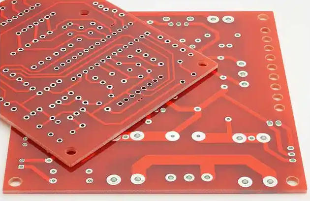
2. Double-Sided PCBs
Now we’re talking. Copper on both sides, connected by plated-through holes — suddenly your routing options multiply.
Double-sided boards are the workhorses of the electronics industry. They hit a sweet spot between cost and capability that makes them the default choice for most medium-complexity designs. Power supplies, industrial controllers, instrumentation — if you’ve opened a piece of professional equipment, you’ve probably seen a double-sided board inside.
Key advantage: Through-hole vias let components on one side connect directly to traces on the other, dramatically reducing the need for jumper wires and making automated assembly practical.
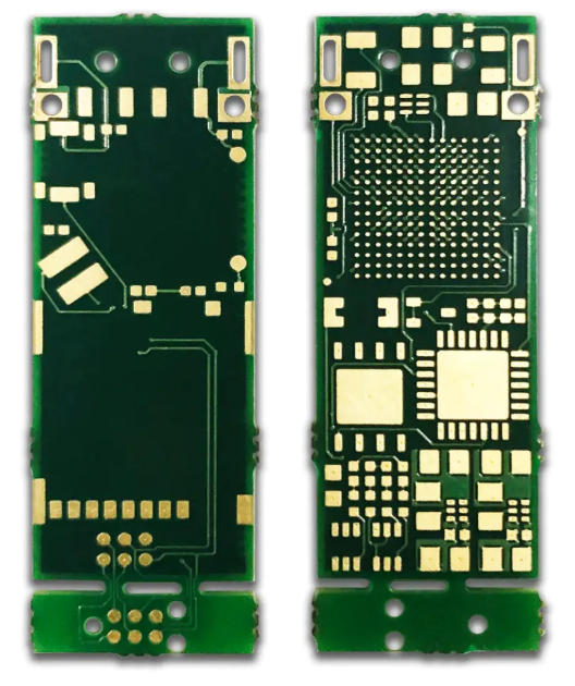
3. Multilayer PCBs
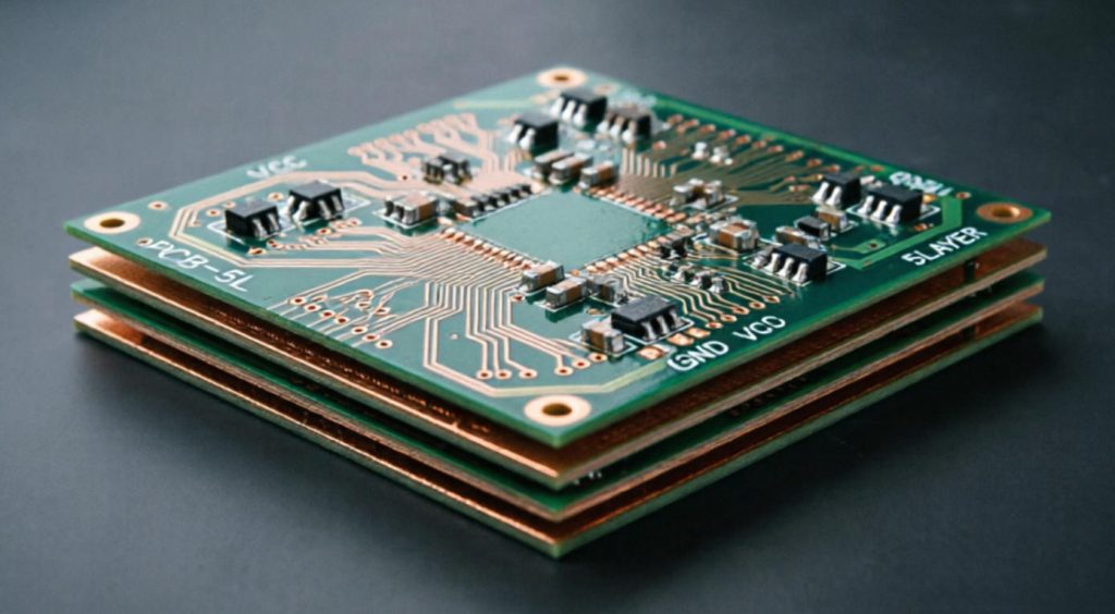
When two sides aren’t enough, you stack more. Four layers is common. Eight, ten, twelve — you keep going until the signal integrity and power distribution demands are met.
Multilayer boards are where things get serious. Internal layers dedicated to ground and power planes provide excellent electromagnetic shielding and controlled impedance — both critical for high-speed digital and RF designs. A modern smartphone motherboard, for instance, might pack ten or more layers into a space thinner than a coin.
The tradeoff: More layers mean higher manufacturing cost, tighter tolerances during lamination, and more thorough testing. For many applications, though, there’s simply no alternative.
Beyond Layers: Specialized PCB Materials & Technologies
Layer count is only half the story. The materials and construction methods used in a board define what environments it can survive and what electrical performance it can deliver.
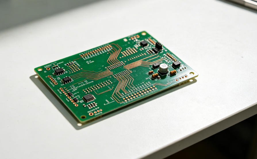
4. Rigid PCBs
This is what most people picture when they hear “circuit board.” A solid, inflexible substrate — usually FR-4 fiberglass — with copper etched into circuit patterns. Rigid boards are the backbone of virtually every electronic device, from your kitchen timer to a military radar system.
Rigid PCBs offer mechanical stability, predictable performance, and a mature manufacturing ecosystem. If your board doesn’t need to bend, fold, or flex, start here.
5. Flexible PCBs
Polyimide substrates replace fiberglass, and suddenly your board can bend, twist, and conform to curved surfaces. Flexible circuits — or “flex boards” — eliminate the need for connectors and cable assemblies in applications where space is measured in millimeters.
Real-world examples: The ribbon cable inside your laptop connecting the keyboard to the motherboard? Often a flex circuit. Medical devices that need to navigate the human body? Flex boards. Camera modules that need to fold into compact housings? You get the idea.
The downside: flex boards cost more to design and manufacture, and they require careful handling throughout the assembly process.
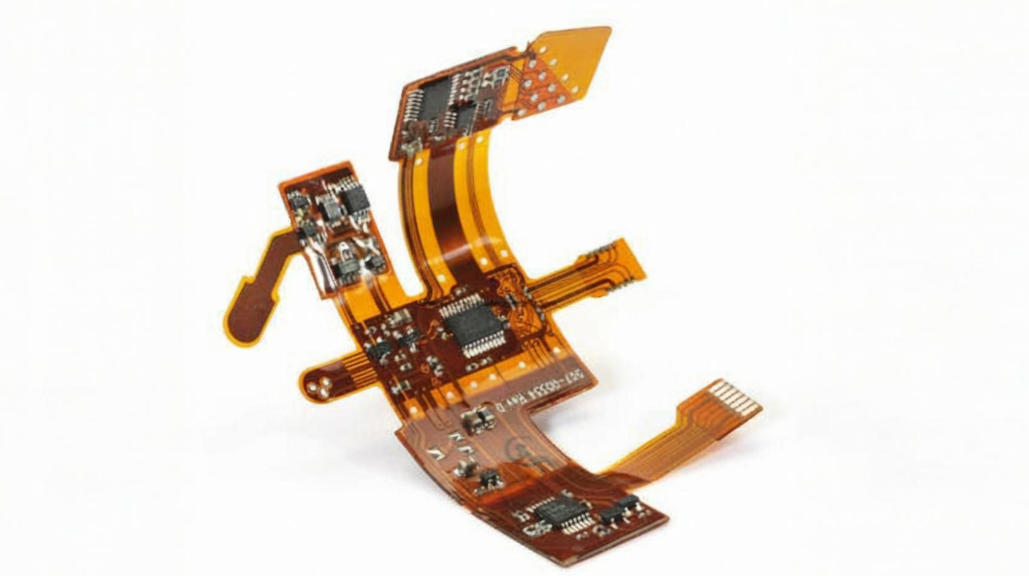
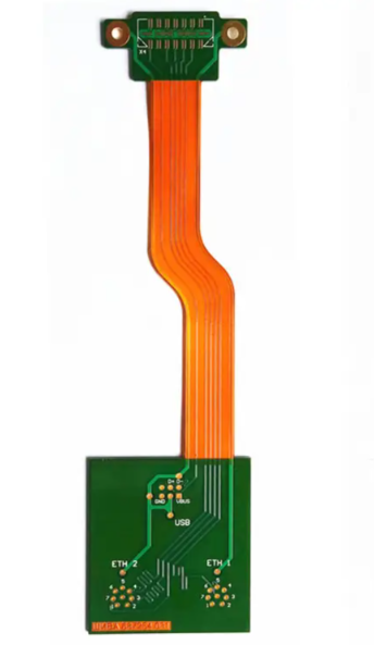
6. Rigid-Flex PCBs
Think of these as the best of both worlds. Rigid sections handle the dense, component-heavy areas while flexible sections bridge between them — eliminating connectors, reducing assembly steps, and creating compact three-dimensional packaging.
We’ve written a dedicated deep-dive on rigid-flex technology covering construction, design considerations, and when exactly to choose this approach. If your project might benefit from rigid-flex, that article is worth your time.
7. Metal Core PCBs / Aluminum PCBs
Heat is the enemy of electronics. When thermal management is the primary concern — particularly in high-power LED lighting, power converters, and automotive lighting modules — metal core PCBs step in.
The structure is straightforward: a thin dielectric layer sits between the copper circuit and an aluminum (or sometimes copper) base plate. The metal base pulls heat away from hot components far more efficiently than standard FR-4 ever could.
Trade-off: You lose the ability to route signals through the metal core, and the dielectric layer limits the board to single or double-sided copper. For purely thermal applications, though, nothing else comes close.
8. High-Frequency PCBs
When your signals run at microwave frequencies — think 5G infrastructure, satellite communications, automotive radar — standard FR-4 starts falling apart electrically. Signal loss climbs, impedance becomes unpredictable, and your beautifully designed RF front-end performs like it was built on a breadboard.
High-frequency boards use specialized laminates with tightly controlled dielectric constants and dissipation factors. Materials like Rogers RO4000 series, PTFE-based substrates, and hydrocarbon ceramics are engineered specifically to move RF energy with minimal degradation.
When you need them: Operating frequencies above roughly 1 GHz, or when insertion loss and phase stability matter for your system performance. Below that threshold, standard FR-4 is usually fine.
9. HDI PCBs (High Density Interconnection)
HDI boards use microvias — laser-drilled holes measured in microns rather than millimeters — along with finer trace widths and spacings to pack more interconnections into less area. The result is a board that supports the extreme miniaturization demanded by modern consumer electronics.
Your smartphone almost certainly has an HDI board inside. Wearable health monitors, compact IoT sensors, military avionics — anywhere board real estate is at a premium and signal counts are high, HDI technology earns its keep.
Cost reality: HDI manufacturing requires specialized equipment and tighter process controls. The per-unit cost is higher, but when your design literally won’t fit on a standard multilayer board, it’s not really a choice.
How to Choose the Right PCB for Your Project
This is where theory meets reality. Knowing what exists is one thing — knowing what you need is another. Here are the questions worth asking before you commit to a board type.
What’s the operating environment? A PCB inside a climate-controlled server room faces very different challenges than one mounted on an engine block. Vibration, temperature extremes, humidity, chemical exposure — these factors drive material selection more than almost anything else.
What are the electrical requirements? High-speed digital, RF, high-current power — each demands different substrate properties. Running a 28 GHz signal through standard FR-4 is a recipe for disappointment.
How much space do you have? If the board needs to fold into a compact housing or fit inside a curved enclosure, rigid-flex or pure flex might be the only path. If space is tight but the board stays flat, HDI could solve the density problem.
What’s your budget? Not just per-unit cost at volume, but NRE (non-recurring engineering) and prototype iteration costs. A complex multilayer or rigid-flex design might take two or three spins to get right. Factor that in.
Let me walk through two real scenarios that illustrate how these decisions play out in practice.
Case Study 1: The Industrial Sensor Manufacturer
A company making environmental monitoring sensors for offshore oil rigs came to us with a problem. Their existing design used a standard four-layer FR-4 board housed in a sealed enclosure, connected to external probes via M12 connectors. In theory, the design was fine. In practice, the connectors were the number one failure point — salt air corrosion, mechanical stress from wave-induced vibration, and water ingress at the connector interface were killing units at an unacceptable rate.
Technical improvements: A hybrid rigid-flex design. The main sensor processing circuitry stayed on a rigid multilayer section, but instead of routing signals out to a connector, flexible circuit extensions ran directly from the board to the probe contact points. The flex sections, sealed with conformal coating, eliminated the mechanical connector entirely.
The result: Unit failure rates dropped by over 70%. Assembly time decreased because technicians no longer had to seat and torque M12 connectors during production. Total cost per unit actually went down slightly once you removed the connector BOM and the associated assembly labor, despite the rigid-flex board costing roughly 40% more than the original FR-4 board.
The takeaway: Sometimes the “more expensive” board saves money when you zoom out to total system cost.
Case Study 2: The Consumer Audio Startup
A small startup developing a portable high-resolution audio player needed to cram a DAC, amplifier, Bluetooth module, battery management circuitry, and a microSD slot into a housing roughly the size of a deck of cards. Their first prototype used a two-layer board with everything crammed onto one side. It worked on a breadboard. On a PCB, it was a mess — crosstalk between the digital Bluetooth section and the analog audio path produced audible noise, and the board physically wouldn’t fit inside the enclosure without the components hanging off the edges.
Technical improvements: Move to a six-layer HDI board with dedicated ground planes separating the digital and analog sections. The finer trace geometries of HDI technology allowed them to fit the complete design into the required footprint, while the internal ground planes provided the isolation the audio circuitry needed.
The result: The crosstalk problem vanished. The board fit the enclosure with margin to spare. The six-layer HDI board cost about three times more than their original two-layer design, but for a product at their target retail price point, the per-unit cost increase was negligible — and the product actually shipped instead of living forever on the whiteboard.
The takeaway: A two-layer board is only “cheaper” if it actually works for your design. When it doesn’t, you’re not saving money — you’re just delaying spending it.
A Quick Decision Reference
| Factor | Single-Sided | Double-Sided | Multilayer | Flex | Rigid-Flex | Metal Core | HDI |
|---|---|---|---|---|---|---|---|
| Cost | Lowest | Low | Medium-High | Medium-High | High | Medium | High |
| Complexity | Simple | Moderate | Complex | Moderate | Very Complex | Moderate | Very Complex |
| Space Efficiency | Low | Medium | High | High | Very High | Low-Medium | Very High |
| Reliability | Standard | Good | Very Good | Good | Excellent | Good | Very Good |
| Typical Use | Basic consumer | Industrial control | Computing, telecom | Wearables, cameras | Aerospace, medical | LED lighting, power | Smartphones, IoT |
Conclusion: Partnering for the Perfect PCB Solution
There’s no universal “best” PCB — there’s only the right board for your specific constraints. A single-sided board makes perfect sense for a simple LED controller. Forcing that same board into a 5G base station is absurd. Conversely, wrapping a consumer product in a rigid-flex assembly when a double-sided board would do the job is just burning cash.
The earlier you involve your PCB manufacturing partner in the decision, the better. An experienced manufacturer doesn’t just build what you send them — they’ll flag design choices that drive up cost unnecessarily, suggest material alternatives you might not have considered, and catch potential reliability issues before they become expensive field failures.
If you’re staring at a blank schematic and aren’t sure which direction to go, or if you’ve already got a design and want a second opinion on material and stackup choices — reach out. A ten-minute conversation about your requirements can save weeks of rework down the line.



0 Comments