




What Is Circuit Card Assembly Testing?
Circuit card assembly testing verifies whether a populated circuit board was assembled correctly and whether it performs the required electrical functions. A circuit card assembly, often shortened to CCA, is a PCB after components have been mounted and soldered. In many manufacturing projects, CCA, PCBA, printed circuit assembly and PCB assembly describe the same practical deliverable.
Testing may include SPI, AOI, X-ray inspection, flying probe, in-circuit testing, boundary scan, firmware programming and functional circuit testing. The important point is this: no single test proves that a circuit card assembly is completely good.
AOI can approve a board that does not boot. A functional test can pass a board with a marginal solder joint. X-ray can show a sound-looking BGA while missing a firmware or communication problem. Reliable testing comes from matching each likely defect to a method that can actually detect it.
| If your assembly has… | Testing to consider first | Why it matters |
|---|---|---|
| BGA, QFN, LGA or bottom-terminated parts | X-ray plus electrical or functional verification | Hidden joints cannot be fully checked by visual inspection alone |
| Firmware, MCU, FPGA or programmable device | Programming verification and FCT | Placement can be correct while the product still fails to run |
| Low-volume or changing prototype design | AOI, selective X-ray, bench bring-up and flying probe | Flexible testing avoids early fixture cost |
| Stable production volume | ICT, boundary scan, programming fixture and automated FCT | Repeatability, cycle time and traceability become more important |
Stop Asking Whether the Boards Are 100% Tested
“Are all boards 100% tested?” sounds like a strong quality question. It usually is not. A manufacturer may truthfully answer yes because every board passed AOI. That does not mean every net was electrically checked, every microcontroller was programmed, every interface was exercised or every output was measured under load.
A useful test requirement must answer four questions:
- Which units will be tested?
- Which characteristics will be measured?
- What are the pass and fail limits?
- What record will be retained?
Replace “100% tested” with something measurable. For example: perform AOI on every assembly, X-ray the specified bottom-terminated components, program every MCU, verify all power rails under load, test the communication interfaces and retain unit-level results by serial number. That sentence is longer, but it is much harder to misunderstand.
What Does Each CCA Test Method Actually Detect?
The main circuit card assembly test methods are complementary rather than interchangeable. Each method has a coverage area and a blind spot. A good test plan names both.
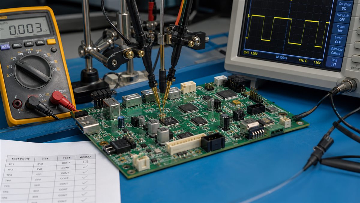
| Test method | Primary purpose | Typical defects detected | Important limitation |
|---|---|---|---|
| SPI | Inspect solder paste before placement | Insufficient, excessive, offset or bridged paste | Cannot inspect the completed solder joint |
| AOI | Inspect visible assembly features | Missing parts, polarity errors, tombstoning, visible bridges and placement errors | Cannot prove electrical operation or fully inspect hidden joints |
| X-ray or AXI | Examine hidden solder structures | BGA opens, shorts, voiding, insufficient solder and head-in-pillow indicators | Does not verify firmware or circuit behavior |
| Flying probe | Electrically access selected nets without a dedicated fixture | Opens, shorts, selected component values and connectivity faults | Slower than fixture-based ICT and restricted by physical access |
| ICT | Electrically test nets and components through a fixture | Opens, shorts, incorrect values, missing parts, orientation faults and selected powered measurements | Requires test access, fixture investment and program development |
| Boundary scan | Access supported digital interconnects through JTAG logic | Digital opens, shorts, inaccessible interconnect faults and programming issues | Requires compatible devices and deliberate boundary-scan architecture |
| FCT | Operate the powered assembly | Power, firmware, I/O, communications, sensors, control logic and outputs | Coverage depends on the customer’s test specification |
| Burn-in or ESS | Screen assemblies under defined stress | Early-life or stress-sensitive failures | Adds time and cost and is not automatically appropriate for every product |
ICT systems stimulate accessible test nodes and measure responses such as resistance, capacitance, diode voltage drop and selected electrical characteristics. Boundary scan can extend coverage to digital nodes that physical probes cannot easily reach. Functional test platforms then evaluate the powered assembly using product-specific measurements and interfaces.
AOI Is Inspection, Not Proof That the Circuit Works
AOI is valuable because it is fast, repeatable and well suited to inline process control. It can detect many placement and visible soldering defects before faulty boards move further through production.
It still cannot answer questions such as:
- Does the 3.3 V rail remain within tolerance under load?
- Does the oscillator start reliably?
- Can the MCU be programmed?
- Does an Ethernet, CAN, USB or UART interface communicate correctly?
- Does an analog input meet its accuracy requirement?
- Does the board draw excessive standby current?
The same warning applies to X-ray. X-ray can inspect solder beneath a BGA or QFN, but it cannot prove that the device contains the correct firmware or that the finished circuit performs its intended operation.
The practical rule is simple: inspection determines whether the assembly appears structurally correct. Electrical testing determines whether selected connections and components behave correctly. Functional testing determines whether the powered board performs the required task.
How Should Testing Change With Production Volume?
Selecting a test method by board complexity alone is a mistake. Production volume, revision stability, failure cost and test time matter just as much.
| Production situation | Practical test strategy | Reasoning |
|---|---|---|
| Early engineering prototypes | Visual inspection, AOI, selective X-ray, bench bring-up and flying probe where practical | The design may change, so expensive fixtures can become obsolete |
| Stable low-volume production | AOI, package-specific X-ray, flying probe or simplified fixture, programming and focused FCT | Flexible coverage is often more valuable than maximum throughput |
| Medium-volume production | AOI, X-ray plan, dedicated programming fixture, FCT and ICT when coverage and economics justify it | Repeatability and cycle time begin to matter more |
| High-volume stable production | Inline process inspection, fixture-based ICT or boundary scan, automated programming, automated FCT and serialized data | Fixture cost can be distributed across more assemblies |
| High-reliability product | Layered structural, electrical, functional and qualification testing based on risk | Field failure consequences outweigh the cost of broader coverage |
Flying probe is attractive when fixture cost or frequent design changes are the main concern. Dedicated ICT becomes more compelling when the product is stable and fast, repeatable test cycles are required. There is no universal quantity where ICT suddenly becomes correct. Board access, fixture complexity, annual volume, test duration and field-failure risk can shift the break-even point.
What Is a Sensible Test Plan for Prototypes?
Prototype testing should produce information, not merely a pass label. A useful prototype sequence is:
- Confirm component placement, polarity and workmanship.
- Inspect hidden-joint packages where necessary.
- Check resistance between main power rails and ground before power-up.
- Apply current-limited power.
- Verify rail sequence and current consumption.
- Confirm reset, clock and programming access.
- Load controlled firmware.
- Exercise critical communication interfaces.
- Apply representative inputs and loads.
- Record failures and update the next revision’s DFT strategy.
The goal is not to automate every check immediately. The goal is to learn which measurements identify defects quickly and which steps should later become part of production FCT. If engineers must probe fine-pitch pins, scrape solder mask from traces or hold wires by hand, the problem is not only testing. It is a testability problem created during design.
What Changes When the Product Enters Production?
A bench procedure that works for ten prototypes may fail badly at 1,000 units. Holding a programming cable against pads by hand, reading LEDs visually or adjusting a load with laboratory instruments may be acceptable during development. In production, those steps introduce operator variation, slow cycle times and weak traceability.
The production version should convert manual judgment into controlled actions:
- Locate the assembly consistently in a fixture.
- Apply power with defined voltage and current limits.
- Program the correct firmware revision automatically.
- Read or assign the serial number.
- Exercise required inputs and outputs.
- Compare measurements against documented limits.
- Save the result against the unit identifier.
- Prevent failed units from proceeding unnoticed.
Any manual step that depends on memory, hand pressure, visual interpretation or copying data should be reviewed before volume production.
Functional Testing Cannot Be Created From Gerber Files Alone
This is one of the most common misunderstandings in circuit card assembly testing. Gerber or ODB++ data tells the manufacturer how the PCB is constructed. A BOM identifies the components. Pick-and-place data gives component coordinates and orientation. None of those files defines what the finished product is supposed to do.
To develop a meaningful functional test, the manufacturer normally needs some combination of:
- Schematic
- Power-up sequence
- Nominal input voltage and current limit
- Expected rail voltages and tolerances
- Firmware and programming instructions
- Communication protocols and commands
- Required loads or simulated sensors
- Input and output conditions
- Calibration process
- Pass and fail limits
- Test duration
- Connector pinout
- Approved golden sample
- Required test-data format
“Power on and check whether it works” is not a test specification. It is an invitation for inconsistent judgment. A good specification states the applied voltage, current limit, expected rails, firmware revision, communication settings, output actions and numerical pass limits.
Design for Test Should Begin Before Layout Is Frozen
Test points are not decoration left over from prototype development. During development, they help engineers observe signals. During manufacturing, they allow fixtures and probes to verify assembly quality. During repair, they shorten fault isolation.
| DFT item | Questions to resolve |
|---|---|
| Power access | Can every important rail be measured safely? |
| Programming | Are programming, reset, boot-mode and ground connections accessible? |
| Communications | Can UART, SPI, I2C, CAN, USB or other critical buses be observed or exercised? |
| Test-point placement | Can probes contact the points without hitting tall components or fixtures? |
| Mechanical support | Will fixture pressure bend the board or stress BGA packages? |
| Boundary scan | Do compatible devices have a usable and documented JTAG chain? |
| Isolation | Can subsystems be isolated when in-circuit measurements would otherwise be masked? |
| Identification | Can the station read or assign a unique unit ID? |
| Firmware support | Is there a production test mode with useful commands and diagnostics? |
| Failure diagnosis | Will a failed test indicate a subsystem, net or measurement rather than only “FAIL”? |
Do this review before final routing. Asking for full test coverage after accessible space has disappeared often leads to restricted coverage, expensive fixtures or an avoidable board revision.
Which Files Should Be Included With a CCA Test Request?
A complete data package reduces quotations based on assumptions. For circuit card assembly testing, send more than the Gerber files.
| File or input | Why it is needed |
|---|---|
| Gerber, ODB++ or IPC-2581 data | Board construction, pads, nets and manufacturing geometry |
| BOM | Component identities, values, tolerances and approved manufacturers |
| Pick-and-place file | Component locations, rotations and reference designators |
| Assembly drawings | Polarity, special installation notes and mechanical details |
| Schematic | Circuit understanding, rail identification, interfaces and test development |
| Netlist | Electrical connectivity and test-program generation |
| Firmware files | Device programming and powered functional test |
| Programming instructions | Device, interface, fuse, security and verification requirements |
| Functional test specification | Inputs, outputs, loads, limits, commands and pass criteria |
| Approved sample | Physical and behavioral reference when appropriate |
| Traceability requirements | Serial number, barcode, log format, retention and report needs |
| Applicable standard and class | Workmanship and acceptance expectations |
The manufacturer should also know whether testing is required on every board or by sampling, whether failed units may be repaired and which test records must accompany the shipment.
Which Test Finds Each Common Assembly Failure?
This table is worth keeping during quotation reviews because it prevents one method from being credited with coverage it does not provide.
| Suspected defect | Most useful detection method |
|---|---|
| Missing resistor or capacitor | AOI, flying probe or ICT |
| Wrong resistor value | Flying probe or ICT |
| Reversed diode or polarized capacitor | AOI plus electrical verification where required |
| Solder bridge on visible leads | AOI or electrical test |
| Hidden BGA bridge or open | X-ray, boundary scan, ICT or FCT depending on access |
| Open net | Flying probe, ICT, boundary scan or targeted continuity test |
| Excessive current draw | Powered ICT or FCT |
| Incorrect rail voltage | FCT or powered ICT |
| MCU not programmed | Programming verification or FCT |
| Wrong firmware version | Programming log or FCT |
| Communication interface failure | FCT |
| Intermittent connector contact | FCT with controlled mating or mechanical stimulation |
| Marginal oscillator start-up | Powered test across defined voltage and temperature conditions |
| Sensor calibration error | Product-specific FCT or calibration station |
| Contamination-related reliability risk | Cleanliness testing and process control, not AOI alone |
A board that works only when pressed with a finger, warmed with a heat gun or flexed is not basically good. That behavior points toward an intermittent solder, package, PCB or mechanical problem that requires diagnosis and corrective action.
What Should a Circuit Card Assembly Test Report Contain?
A report that only states “PASS” provides little help when a field return appears months later. Useful unit-level records may include:
- Assembly part number and revision
- Serial number or traceability code
- Test date and station
- Test-program revision
- Fixture revision
- Firmware version
- Individual measurement results
- Acceptance limits
- Overall pass or fail status
- Failure code or failed step
- Rework and retest history
- Operator or automated station identification
For prototypes, a concise report may be sufficient. For regulated or high-reliability programs, the customer may require stronger revision control, retention periods, calibration records and links between material lots, production processes and test results. Traceability should be agreed before production, not reconstructed after shipment.
How Do You Evaluate a Manufacturer’s Testing Capability?
Do not judge a supplier by the length of its equipment list. A factory can own AOI, X-ray, flying probe and functional-test equipment while still lacking a sensible test strategy for your product.
Ask questions that reveal how the process will actually work:
- Which defects will each proposed test detect?
- Which important faults remain uncovered?
- Is testing performed on every board or by sampling?
- Are BGA and QFN locations inspected automatically or selectively?
- Does the proposed electrical test require added test points?
- Who develops and approves the functional test procedure?
- Who supplies firmware, loads, cables, mating connectors and reference units?
- How are fixture and test-program revisions controlled?
- Are numerical measurements stored or only pass and fail results?
- How are failed boards diagnosed, repaired and retested?
- Can the test station identify the correct hardware and firmware revision?
- What evidence will be delivered with the shipment?
The best answer is rarely “we test everything.” A competent manufacturer should explain the coverage, limitations, inputs, cost and expected output of the proposed plan. If a test adds cost but does not address a credible failure mode, it may not be worth adding. If a serious defect can escape the current plan, another inspection method, design change or functional check may be necessary.
Frequently Asked Questions
What is the difference between CCA testing and PCBA testing?
In most manufacturing projects, CCA testing and PCBA testing describe the same activity: inspecting and verifying a populated printed circuit board. CCA is common in formal documentation and high-reliability sectors, while PCBA is more common in general electronics manufacturing.
Is AOI enough for circuit card assembly testing?
No. AOI is effective for visible placement and soldering defects, but it cannot prove that the circuit operates correctly. Assemblies with firmware, communications, power rails, sensors or outputs normally need additional electrical or functional verification.
What is the difference between flying probe and ICT?
Flying probe uses moving probes and normally avoids a dedicated bed-of-nails fixture. It is flexible for prototypes and changing designs but has a longer test cycle. ICT generally uses a dedicated fixture, offering faster production testing once the design is stable.
Can flying probe test every component?
Not necessarily. Coverage depends on accessible pads, vias, component leads, circuit topology, component type and available design data. Parallel paths and inaccessible nodes can limit component-level measurements.
Does X-ray inspection guarantee that a BGA is good?
No. X-ray can identify many hidden-joint conditions, including bridges, voiding, alignment problems and some opens. It does not prove that the BGA device functions correctly, contains valid firmware or communicates with the rest of the circuit.
Is functional testing required for every PCBA?
Not every assembly needs the same level of FCT. However, when product behavior, firmware, interfaces, sensing, power conversion or safety-related outputs matter, functional testing is often the most direct way to confirm the required operation.
Who should provide the functional test procedure?
The product owner should define what the assembly must do and the acceptable limits. The manufacturer can help convert those requirements into a fixture, test program and production sequence, but it should not be expected to invent undocumented product behavior.
When should test points be added to a PCB?
Test access should be reviewed during schematic and layout development, before routing is finalized. Waiting until production quotation often results in restricted coverage, complicated fixtures or an avoidable board revision.
Should every board receive burn-in testing?
No. Burn-in and environmental stress screening should be selected according to product risk, component behavior, reliability requirements and an approved procedure. Applying stress without a defined objective can add cost without producing useful evidence.
What should be included in a circuit card assembly testing quotation?
The quotation should identify the test methods, fixture or programming charges, test-program development, per-board test time, sampling or full-test requirement, customer-supplied items, acceptance criteria, traceability output and treatment of failed units.
Build a Test Plan Before the First Production Failure
PCBtry supports PCB manufacturing and assembly projects where inspection, programming, functional verification and testability review need to be considered before production begins. Instead of adding every available test to the quotation, the stronger approach is to review assembly structure, component packages, test access, production volume and functional requirements first.
For a PCBA testability review, send your Gerber or ODB++ data, BOM, pick-and-place file, schematic, firmware, available test specification and any golden sample requirements through the PCBtry contact page. For assembly projects, also review the PCB assembly service information so the quotation can separate inspection, electrical testing, functional testing and customer-supplied test inputs clearly.



1 Comment
When to Use an Evaluation Board vs Custom PCB Design: A Stage-Gate Guide - thindry pcb manufacturer · 08/26/2026 at 08:36
[…] Once the stage-gate decision supports custom hardware, prepare controlled fabrication and assembly inputs: schematic and PCB files, Gerbers or ODB++ as applicable, drill data, stackup and impedance requirements, board outline, material and finish, BOM with manufacturer part numbers, placement data, drawings, quantity, inspection expectations and test requirements. For related next steps, review PCBtry’s guides to custom PCB files and quote checks, moving a prototype into PCB design, and circuit-card assembly test coverage. […]