




What Is FR4?
FR4 is the most common insulating laminate family used for rigid printed circuit boards. It is made from woven glass cloth and epoxy resin, then combined with copper foil to create copper-clad laminate, cores, prepreg and multilayer PCB stackups. In everyday PCB buying, people often say “FR4 board” when they mean a rigid PCB built on a glass-epoxy material base.
The important point is that FR4 is a material category, not a single universal datasheet. Two boards can both be called FR4 while using different resin systems, glass styles, Tg values, dielectric behavior, copper construction and thickness tolerance. For a simple controller board that difference may not matter much. For impedance control, repeated lead-free assembly, dense vias, RF routing or high operating temperature, it can matter a lot.
A useful way to think about FR4 is this: FR4 gives the PCB mechanical support, electrical insulation and a manufacturable base for copper circuitry. Copper carries signals and current; FR4 separates copper layers, supports holes and vias, and helps the board survive fabrication, assembly and use.
Why FR4 Became the Default PCB Material
FR4 is widely used because it balances cost, availability, strength, insulation and process familiarity. PCB factories know how to drill, plate, laminate, route, solder mask and assemble standard FR4 boards at scale. Designers also have a large ecosystem of stackups, design rules and manufacturing tolerances built around FR4.
That does not mean FR4 is always the best material. It means FR4 is often the best starting point. A buyer should start with the product risk, not with the cheapest material name. Ask whether the design has high frequency loss limits, controlled impedance, thermal stress, voltage spacing, repeated reflow, high current, thin traces, dense vias or a harsh operating environment. If none of those are severe, standard FR4 may be enough. If one of them is important, the exact FR4 grade or an alternative laminate may need review.
FR4 Structure: What Is Inside the Board?
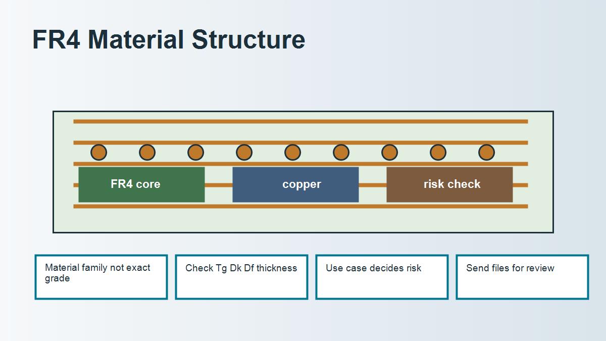
A finished FR4 PCB is not just one green plate. The visible green surface is usually solder mask. Under that are copper traces and pads. Under or between copper layers are FR4 dielectric layers. In multilayer construction, some layers are cured cores and some are prepreg that flows and cures during lamination. The final board thickness depends on core thickness, prepreg selection, copper weight, layer count, press cycle and fabrication tolerance.
This structure is why a drawing that says only “FR4, 1.6 mm” can still leave important questions unanswered. The factory may still need to know finished thickness tolerance, copper weight, Tg requirement, impedance targets, stackup notes, soldering process and whether material substitution is allowed.
Important FR4 Properties Buyers Should Understand
| Property | What it means | Why it matters for PCB buyers | Common mistake |
|---|---|---|---|
| Tg | Glass transition temperature range of the resin system | Helps assess thermal margin for assembly and operation | Using Tg alone as the whole reliability decision |
| Dk | Dielectric constant under a stated test condition | Affects impedance and signal propagation | Treating one Dk number as valid at every frequency |
| Df | Dissipation factor, related to dielectric loss | Matters for high-speed and RF signal loss | Ignoring trace length, copper roughness and vias |
| CTE | Thermal expansion behavior | Influences plated-hole and via reliability | Comparing values without axis and temperature range |
| Thickness | Finished board thickness and tolerance | Affects enclosure fit, impedance and mechanical stiffness | Assuming nominal thickness is the exact delivered value |
Each property needs context. A datasheet value should be tied to material grade, test method and application. If the board is low speed and mechanically simple, over-specifying a premium material can add cost without solving a real problem. If the board is sensitive, under-specifying FR4 can create assembly or performance risk.
FR4 vs Other PCB Material Options
| Material option | Best used for | Main advantage | Main limitation | Buyer decision |
|---|---|---|---|---|
| Standard FR4 | General rigid PCBs | Cost-effective and widely available | Limited high-frequency loss control | Use when performance risk is normal |
| High-Tg FR4 | Lead-free assembly or higher thermal stress | Better thermal margin than standard FR4 | Still not automatically low-loss | Use when heat reliability matters |
| Low-loss laminate | RF and high-speed channels | More predictable Dk/Df behavior | Higher cost and tighter process needs | Use when loss budget or impedance risk is real |
| Metal-core PCB | LED and heat-spreading designs | Shorter heat path to metal base | Different routing and isolation limits | Use when heat removal dominates |
| Ceramic PCB | High power, RF or high temperature applications | High thermal conductivity and stability | Higher cost and mechanical constraints | Use only when organic laminate is not enough |
Real PCB Case: When “FR4” Was Too Vague
A buyer sent a four-layer industrial control board for quotation. The drawing said “FR4, 1.6 mm” and the Gerber files looked ordinary at first glance. During engineering review, the board showed dense through holes, 2 oz copper, lead-free assembly and a compact enclosure with limited airflow. The material name was not the real issue. The risk was whether the chosen laminate, hole structure and copper balance would survive assembly and temperature cycling.
The factory asked for operating temperature, reflow profile, finished copper weight, finished thickness tolerance and whether high-Tg FR4 was required. After review, the buyer approved a high-Tg FR4 option and accepted a controlled stackup instead of using the cheapest default material. The change did not turn the board into an exotic design, but it reduced reliability risk before mass production.
Buyer takeaway: if heat, thick copper, many vias or lead-free reflow are involved, do not specify only “FR4.” Tell the PCB supplier the assembly and operating conditions so the right FR4 grade can be selected.
FR4 Quote Checklist Before Ordering
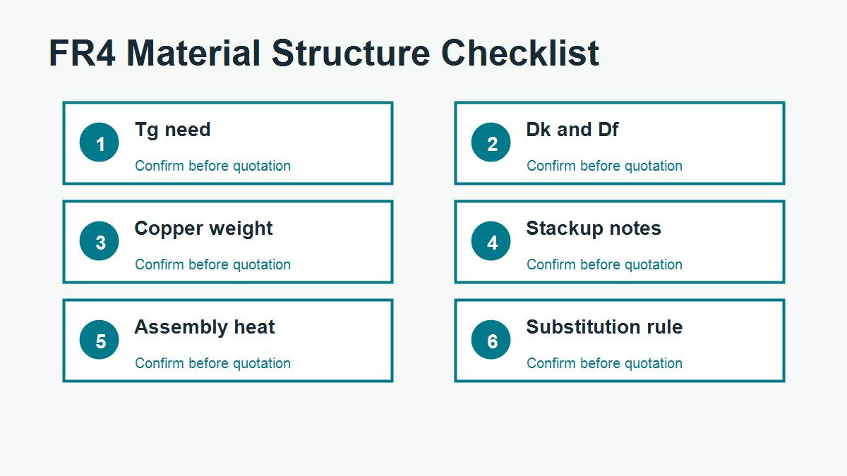
- Confirm whether standard FR4 is acceptable or high-Tg FR4 is required.
- Provide finished board thickness and tolerance, not only nominal thickness.
- State copper weight for each layer, especially if heavy copper is used.
- Send impedance targets and stackup requirements when Dk matters.
- Tell the supplier the assembly process, reflow exposure and operating environment.
- Ask whether material substitution is allowed for prototypes and production.
- Send Gerber, drill, stackup, BOM if assembly is included, and any reliability notes.
Related FR4 Guides
For a deeper material selection workflow, read the PCB FR4 material guide. If your main concern is electrical behavior, review the FR4 dielectric constant guide. If you need to read supplier material data, use the FR4 datasheet guide.
Ask PCBTRY to Review Your FR4 Requirement
If you are not sure which FR4 grade is suitable, send PCBTRY your Gerber files, stackup notes, copper weight, finished thickness, operating environment and quantity. PCBTRY can review whether standard FR4 is enough or whether the design needs high-Tg, low-loss, metal-core, ceramic or another material route before production.
Common FR4 Mistakes That Cause Quote or Production Problems
The most common FR4 mistake is treating a short material word as a complete production requirement. A PCB supplier cannot reliably quote every risk from the phrase “FR4” alone. The quote also depends on board thickness, layer count, copper weight, surface finish, hole structure, impedance, assembly process, test requirement and delivery quantity. If those details are missing, the first quote may look fast but the order can still change after engineering review.
A second mistake is comparing suppliers only by unit price. One quote may assume standard FR4, loose tolerance and no special report. Another quote may include high-Tg material, impedance coupon, tighter inspection or a controlled stackup. If the assumptions are different, the prices are not truly comparable. Buyers should ask what is included before deciding that one supplier is more expensive.
A third mistake is using a datasheet value without checking how the finished board will be built. Dk, Df, Tg and CTE values are useful, but they must be connected to the actual stackup, copper construction, press process and assembly exposure. For sensitive designs, the better workflow is to share the real files and let the manufacturer confirm a practical build.
Questions to Send With an FR4 PCB RFQ
| Question | Why it helps | What the supplier can confirm |
|---|---|---|
| Is standard FR4 acceptable for this application? | Prevents over-specifying or under-specifying material | Material family, Tg need and substitution rule |
| Can you propose a manufacturable stackup? | Connects material to real production | Core, prepreg, copper and thickness tolerance |
| Does this board need impedance control? | Protects signal integrity requirements | Trace geometry, Dk assumption and coupon options |
| Are there DFM risks in the files? | Finds issues before production | Drill, spacing, annular ring, solder mask and outline risks |
| What should be changed before mass production? | Turns the quote into a decision tool | Cost, yield, testing and reliability improvements |
FR4 FAQ for PCB Buyers
Can I simply write FR4 on the drawing?
You can do that for many simple boards, but it is not enough for every project. If the board has controlled impedance, high assembly temperature, heavy copper, dense vias, RF signals or strict reliability requirements, add the relevant material and stackup notes.
Does higher Tg always mean better FR4?
Higher Tg can improve thermal margin, but it does not automatically solve signal loss, impedance, current carrying or moisture concerns. Match the material upgrade to the actual risk.
Should prototypes and mass production use the same FR4 grade?
For low-risk prototypes, an equivalent stocked FR4 may be acceptable. For controlled or certified products, keep the material rule consistent and document any approved substitution before production.
How This FR4 Page Should Be Used as a Starting Point
Use this page as the general decision map, then move to the narrower page that matches the problem you actually have. If you need a material definition, stay with the basics. If you need a quote, prepare the RFQ details. If you need impedance control, focus on Dk, dielectric thickness and stackup. If you need thermal reliability, review Tg, CTE, hole structure and assembly exposure. If you need physical weight, calculate board area, thickness, copper and packaging.
This avoids a common SEO and purchasing problem: reading six similar FR4 explanations but still not knowing what to send to the factory. The practical output should be a clearer engineering note, a cleaner RFQ and fewer surprises after the supplier reviews the files.
How to Decide Whether FR4 Is Enough
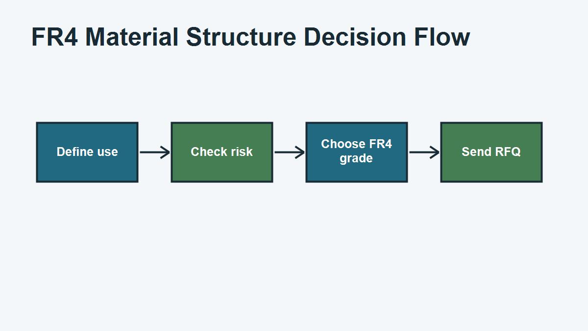
Use a simple risk filter before asking for a quote. If the board is low speed, moderate temperature, normal copper weight and ordinary thickness, standard FR4 is usually a reasonable baseline. If the board has controlled impedance, long high-speed routes, RF sections, dense plated holes, heavy copper, repeated lead-free reflow, high voltage spacing or a tight enclosure, ask the supplier to review the material instead of assuming standard FR4.
The decision should be documented in the RFQ. A short note such as “standard FR4 acceptable unless engineering review finds thermal or impedance risk” gives the factory permission to flag issues. A stricter note such as “high-Tg FR4 required, substitutions need approval” protects production consistency. The right wording depends on product risk, not on habit.



0 Comments