




How do you flash a PCB?
You do not flash the bare PCB itself. You write firmware into a programmable device mounted on the assembled board, such as a microcontroller or external flash memory. Identify the exact device and programming interface, verify voltage and pinout, load the correct firmware image, program it with the supported tool, then verify both the written data and board behavior.
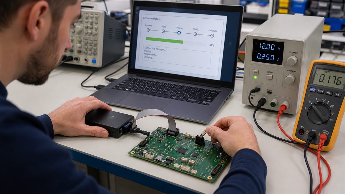
What part of a PCB is actually flashed?
Firmware is stored in nonvolatile memory. That memory may be inside the MCU, in a separate SPI flash device, or behind a bootloader exposed through USB or UART. A board photo alone is not enough to choose a method. Read the component marking, schematic, BOM and device datasheet first.
Identify the target device and interface
| Interface | Typical signals | Common use | Critical check |
|---|---|---|---|
| SWD | SWDIO, SWCLK, GND, reference voltage, optional reset | ARM MCUs | Logic voltage and debug access state |
| JTAG | TMS, TCK, TDI, TDO, GND, reference voltage | MCUs, processors, boundary scan | Pin order and chain configuration |
| ISP/SPI | MOSI, MISO, clock, select/reset, power reference | AVR or external flash | Other circuitry loading the bus |
| UART bootloader | TX, RX, GND and boot/reset control | Factory ROM bootloaders | Cross TX/RX and correct I/O voltage |
| USB DFU/QMK | USB data and bootloader entry | Keyboards and USB devices | Correct bootloader and firmware target |
These signal names are examples, not a wiring instruction. Use the exact datasheet and board documentation because connectors may reorder pins.
Prepare the firmware, programmer and records
- Exact PCB revision and populated BOM revision
- Target part number and memory map
- Approved firmware file, version and cryptographic checksum
- Programmer model, adapter and supported software version
- Programming configuration: address, erase mode, option bytes, fuses or security settings
- Acceptance test and a recovery image
Do not flash an image merely because its filename looks familiar. A valid file for another hardware revision can program successfully and still damage peripherals or leave the product unusable.
Check power and connections before programming
Inspect for reversed connectors, solder bridges and missing grounds. Decide whether the programmer powers the target or only senses its voltage; never connect two uncontrolled power sources. With current limiting enabled where appropriate, confirm that the board supply and programmer I/O levels match the device limits before attaching signal pins.
Enter the bootloader or debug mode
The entry method is platform-specific. It may require a BOOT strap during reset, a reset button sequence, a USB DFU command, a QMK reset key, or direct debug access. Record the known-good sequence. If the computer never detects the device, verify power, cable data capability, driver, boot strap and clock requirements before repeatedly erasing the target.
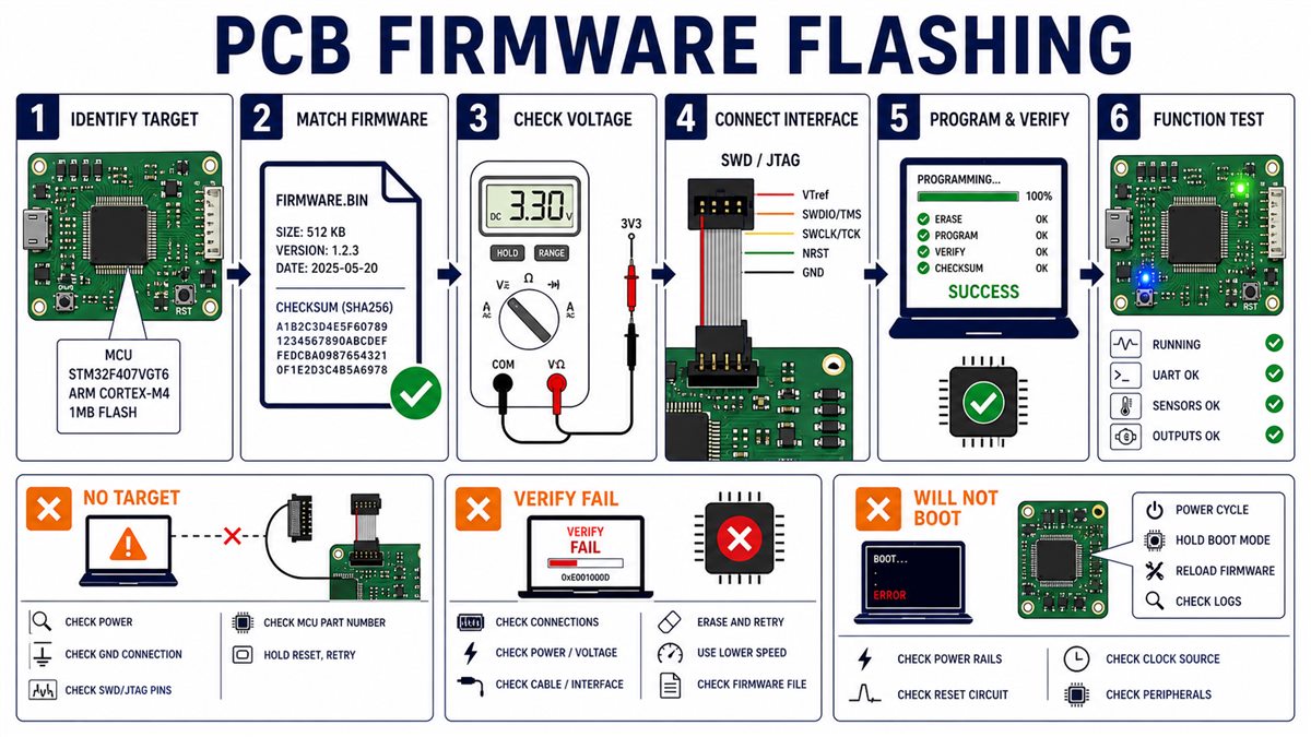
Flash the firmware step by step
- Archive the approved image and checksum with the board revision.
- Connect ground and voltage reference before programming signals.
- Start the supported programming tool and select the exact target.
- Read the device ID when the tool supports it; stop if it does not match.
- Erase only the required region and preserve calibration data when specified.
- Program the image and enable tool-level verify.
- Disconnect safely, power-cycle the board and run the acceptance test.
Verify more than the programmer message
A tool-level verify compares programmed memory with the file, but it does not prove the whole board works. Confirm boot behavior, version reporting, communications, key inputs and safety-critical outputs. For production, save serial number, firmware version, checksum, programmer result, operator or station ID and test result.
Troubleshoot common flashing failures
| Symptom | Likely cause | Next check |
|---|---|---|
| No target detected | No power/reference, wrong pins, reset held, interface disabled | Measure target voltage and verify pinout |
| Device ID is wrong | Wrong target selection, bus contention or connection error | Stop and confirm part marking and interface |
| Programming stops midway | Unstable power, poor contact, cable noise or protection | Check current log, fixture and erase protection |
| Verify fails | Write protection, bad memory, wrong address or unstable link | Read back safely and compare configuration |
| Verify passes but board will not boot | Wrong image/revision, boot configuration, clock or hardware fault | Check reset, rails and the PCB test sequence |
Design a PCB for reliable programming
Expose labeled test pads or a keyed header for power reference, ground, reset and programming signals. Keep access clear of tall parts, define fixture datums and ensure the programming bus is not heavily loaded. For production, pogo-pin fixtures reduce connector wear and reversed hookups.
Prepare firmware flashing for PCBA production
Give the assembler the exact image, checksum, board revision, target device, programmer/configuration, security settings, serialization rule and acceptance test. Include Gerber and drill data plus assembly files; review the PCB Gerber file package before release. State whether programming happens before or after final assembly and how failures are quarantined.
Pre-flash checklist
- Board revision and target part match the release package.
- Firmware checksum matches the approved value.
- Programmer supports the target and I/O voltage.
- Pin 1, ground and voltage reference are confirmed.
- Only one controlled source powers the target.
- Protection, fuse and option-byte changes are documented.
- Tool verify and functional acceptance tests are defined.
- A recovery path exists before security is locked.
Frequently asked questions
Can every PCB be flashed?
No. The assembled board must contain a programmable device and provide an accessible bootloader or hardware programming interface.
Can I flash a PCB through USB?
Only if its MCU and firmware provide a compatible USB bootloader such as DFU or a board-specific loader.
Is QMK Toolbox suitable for any PCB?
No. It is intended for supported keyboard controllers and bootloaders. Use the tool specified for the actual target device.
What is the difference between flashing and programming?
They are often used interchangeably. Flashing usually emphasizes writing nonvolatile flash memory; programming can also include fuses, option bytes, EEPROM and serialization.
Can the programmer power the board?
Some can provide limited target power, while others only sense voltage. Follow both programmer and board specifications and avoid competing supplies.
Why does flashing pass but the PCB not work?
The image may target another revision, configuration data may be missing, or the hardware may have power, reset, clock or assembly faults.
Should firmware be loaded before or after assembly?
It depends on device access and test strategy. Many PCBAs are programmed after assembly so the process can be followed immediately by functional testing.
What files does a PCBA factory need for programming?
Provide the approved binary or hex file, checksum, target and board revision, programmer settings, security configuration, serialization rule and acceptance test.
Can flashing permanently lock the MCU?
Security bits, readout protection or incorrect fuses can restrict later access. Confirm a recovery plan before enabling irreversible settings.
Request PCB assembly and programming review
For a programmed PCBA quote, send the Gerber and drill files, BOM, placement file, assembly drawing, firmware image and checksum, target/programmer details, quantity and acceptance test through the PCBtry contact page. Engineering review can check programming access and manufacturing data before the build.



0 Comments