




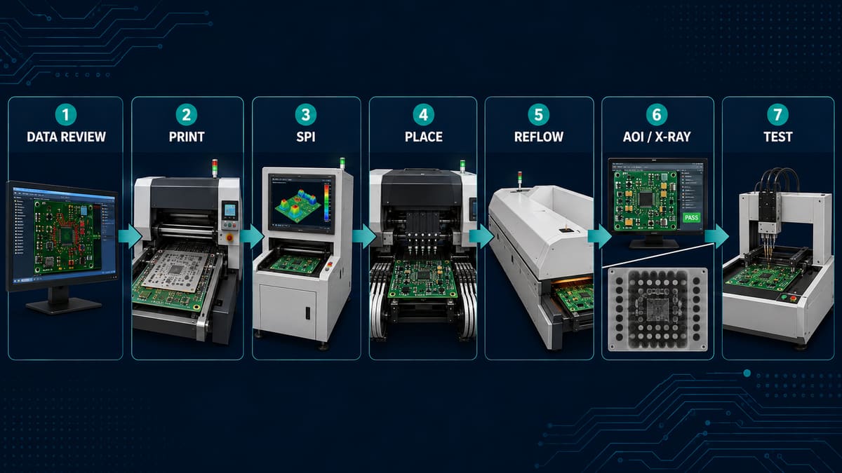
The automated PCB assembly process uses programmed printing, placement, soldering and inspection equipment to convert a bare PCB and components into a repeatable PCBA. A typical SMT route is solder-paste printing, SPI, pick-and-place, reflow and AOI, followed by selective X-ray and electrical or functional testing. Automation improves consistency and throughput, but only when the BOM, placement data, stencil, program, profile and acceptance rules are controlled.
PCBTRY can review Gerber data, BOM, CPL/centroid files, assembly drawings and test requirements before quotation. Early DFM/DFA review prevents an automated line from repeating the same file, polarity or process error across an entire lot.
What Is an Automated PCB Assembly Process?
It is a connected manufacturing route in which machines transfer boards, print paste, inspect deposits, place parts, solder joints and collect inspection data. Manual work may still be required for odd-form components, rework, visual confirmation and product-specific tests. “Automated” describes controlled repetition, not the absence of engineering decisions.
How Does the Automated PCB Assembly Process Work?
1. Engineering and data review. Engineers reconcile Gerber, BOM, CPL, drawings, polarity, substitutions, panelization and test instructions. Missing coordinates or a wrong package mapping will be reproduced accurately by the machine, so approved data and first-article records are the buyer evidence.
2. Material preparation and traceability. Bare boards, components, paste and stencils are verified against revision and handling requirements. Moisture-sensitive parts, wrong feeder lots or expired/poorly conditioned paste create defects that downstream inspection may not fully recover.
3. Board loading and alignment. The panel enters the printer using rails, tooling and fiducials. Warpage or unstable support shifts the board relative to the stencil; line setup and fiducial recognition should be checked before volume release.
4. Solder-paste printing. A controlled squeegee stroke transfers paste through stencil apertures. Stencil design, support, paste condition, pressure and cleaning affect deposit volume and position; poor printing drives bridging, opens and tombstoning.
5. Solder-paste inspection. SPI measures deposit presence, position, height or volume according to the system and program. Its purpose is early feedback to printing, not merely sorting boards. Trend records and reaction limits show whether the process is corrected before placement.
6. Automated component placement. Feeders, nozzles and vision systems pick, identify, rotate and place components from CPL coordinates. Wrong feeder setup, nozzle choice, package data or polarity creates missing, skewed, rotated or damaged parts. First-article comparison and feeder verification are essential.
7. Reflow soldering. The populated panel passes through a profiled oven so paste activates, melts, wets and solidifies. The profile must suit the paste, board thermal mass and component limits; imbalance can produce non-wetting, voiding, tombstoning or heat damage.
8. Optical and X-ray inspection. AOI checks optically visible placement and joint features; X-ray is selected for hidden joints such as bottom-terminated packages. Programs require validation because false calls and missed defects can coexist. Defect images should feed root-cause action, not just rework.
9. Through-hole, odd-form and secondary operations. Mixed-technology assemblies may add insertion, selective or wave soldering, cleaning, coating or depaneling. These are not automatically eliminated by an SMT line and need their own fixtures and acceptance rules.
10. Electrical test and release. ICT, flying probe, programming or functional test confirms conditions that cameras cannot see. The selected coverage depends on product risk and access. Results, serial/lot traceability, deviations and rework history support shipment approval.
What Files Drive Automated PCB Assembly?
| File | Machine or decision | Critical checks |
| Gerber/ODB++ and drill | Board and stencil context | Revision, origin, outline and layers |
| BOM | Purchasing and feeder setup | MPN, quantity, package, substitutions |
| CPL/centroid | Placement program | Reference, X/Y, rotation, side and origin |
| Assembly drawing | Polarity and special instructions | Pin 1, DNP, orientation and hardware |
| Test specification | ICT/FCT/programming | Coverage, limits, firmware and records |
How Are Solder Paste and Stencil Printing Controlled?
Printing is controlled as a process, not judged only by appearance. Match apertures to pad and component needs, support the panel, manage paste condition and cleaning, then use SPI trends to adjust the source. Repeated bridging at one location may point to aperture or gasketing; broad volume drift may point to paste, pressure or cleaning.
How Does Pick-and-Place Automation Prevent Errors?
Vision verifies parts and fiducials, while program data controls coordinates and rotation. Prevention still depends on feeder-to-BOM verification, package libraries, nozzle selection and first-article approval. The correct component placed at the wrong polarity remains a program error, not a machine accuracy problem.
What Controls Reflow Soldering Quality?
The actual product profile controls soldering quality. Board thickness, copper, component mass, paste and loading affect heating. Verify the profile on a representative assembly and define rules for recipe changes; oven temperature settings alone do not prove the joints saw the intended thermal cycle.
What Is the Difference Between SPI, AOI and X-Ray?
| Method | Checks | Cannot prove alone |
| SPI | Printed paste deposits | Final joint or electrical function |
| AOI | Visible placement/joint features | Hidden joints and circuit behavior |
| X-ray | Hidden joint structure and void patterns | Firmware or full function |
| ICT/flying probe | Selected nets/components | Complete use-case behavior |
| Functional test | Specified powered behavior | Every latent workmanship risk |
What Defects Can an Automated Line Still Produce?
Automation can repeat insufficient paste, bridging, skew, tombstoning, polarity errors, wrong parts, non-wetting and hidden-joint defects. Investigate the creating process first: print defects at the printer, placement offsets in feeders/nozzles/programs, and solder defects in paste/profile/design interaction. Rework without root-cause closure hides process drift.
How Does Design Affect Automated Assembly?
Fiducials, panel rails, component spacing, thermal balance, stencil apertures, test access and clear polarity markings determine whether automation is stable. DFM/DFA should also review bottom-terminated packages, tall parts, edge components and mixed processes before stencil and fixtures are released.
What Traceability Should Buyers Request?
Traceability should connect the shipped assembly to the approved revision, bare-board lot, component lots where required, machine program/profile revision, inspection/test results and rework or deviation records. The appropriate depth depends on product risk and contract requirements.
How Long Does Automated PCB Assembly Take?
Lead time depends on component availability, programming, stencil/fixture readiness, first-article approval, inspection/test coverage and lot size. A fast line cannot compensate for unresolved BOM alternates or missing test software. Ask for the schedule after data and materials are complete.
How Do You Choose an Automated PCB Assembly Supplier?
Ask how the supplier validates BOM/CPL data, approves first articles, links SPI/AOI results to process correction, selects X-ray and electrical tests, controls program changes and records rework. Equipment lists matter less than demonstrated control of the full route.
Automated PCB Assembly RFQ Checklist
- Gerber/ODB++, drill and stackup
- Approved BOM with MPNs and substitution rules
- CPL with origin, rotation and side convention
- Assembly drawings, DNP and polarity notes
- Panel or panelization constraints
- Stencil and special solder requirements
- Programming files and instructions
- Inspection/test coverage and acceptance criteria
- Traceability, report, packaging and quantity needs
Frequently Asked Questions
Is automated PCB assembly only for high volume?
No. Automated printing and placement can also support prototypes and high-mix work, but setup and first-article effort remain significant.
Does AOI replace functional testing?
No. AOI evaluates visible features; functional testing checks specified powered behavior.
Why is SPI placed before pick-and-place?
It detects printing variation before components consume more value and obscure the paste.
When is X-ray needed?
Use it when hidden-joint risk or the acceptance plan requires evidence that optical inspection cannot provide.
Can the assembly house create the CPL?
It may derive data, but the customer should verify reference, origin, rotation, polarity and side against the approved design.
What is first-article inspection?
It verifies the initial built unit or panel against approved data before normal lot continuation.
Does automation eliminate rework?
No. A controlled process reduces defects; defined rework and root-cause closure are still needed.
What is needed for quotation?
Send fabrication data, BOM, CPL, drawings, quantities and inspection/test requirements.
Request an Automated PCB Assembly Review
Send Gerber/ODB++, BOM, CPL, assembly drawings, quantities and test requirements through the PCBTRY contact page. The engineering review can identify data, stencil, placement, inspection and test gaps before line setup.



0 Comments