




A useful PCB assembly QC process flow chart connects production steps to inspection gates, acceptance evidence and a controlled response when something fails. It should not show only “SMT → AOI → test → shipment.” It must show what is approved before each stage, what is measured, who releases the lot and where nonconforming material goes.
The example below is a starting framework for prototypes and repeat production. Adapt sampling, workmanship criteria, test coverage and records to the product and purchase specification. PCBTRY can review your Gerber data, BOM, placement file, drawings and test requirements to build a project-specific control route and quotation.
What Should a PCB Assembly QC Flow Chart Show?
The chart should show five elements at every meaningful gate: required input, production action, inspection or test, acceptance decision and retained record. A line of machine names describes routing; a QC chart explains control.
| Flow-chart element | Question it answers | Example |
|---|---|---|
| Input | What must be approved? | Released BOM, CPL and assembly drawing |
| Process | What transforms the product? | Solder-paste printing or reflow |
| Quality gate | What is checked now? | SPI deposit result or first-article polarity |
| Decision | Who can accept, hold or reject? | Quality/engineering disposition |
| Record | What proves the decision later? | Inspection result tied to lot or serial number |
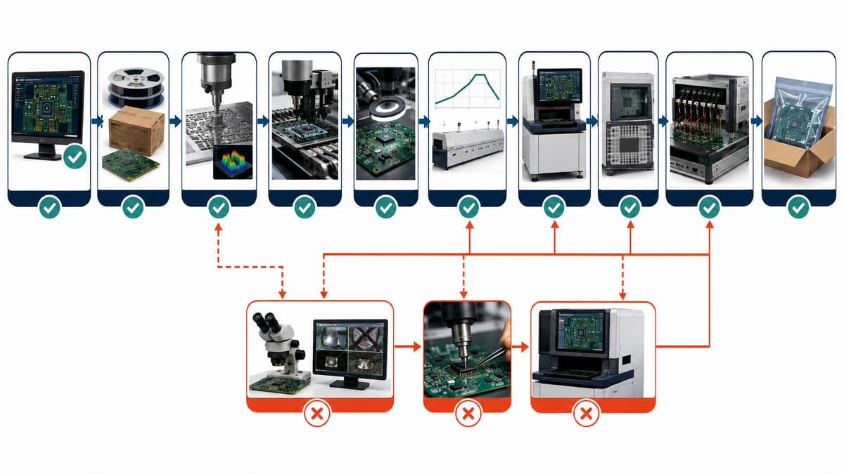
PCB Assembly QC Process Flow Chart Example
The practical sequence below places checks at the earliest stage that can contain each defect.
1. Contract and data review. Confirm revision, quantity, workmanship reference, approved alternates, programming, test, coating, packing and required evidence. Hold the job when BOM, Gerber and placement data conflict.
2. Incoming quality control. Verify bare-board identity and release status, component part numbers, quantities, packaging, moisture controls and customer-supplied material condition. Segregate discrepancies before kitting.
3. Line setup and first article. Verify stencil, paste, feeder setup, placement program, polarity and reference designators against the released package. Production release should require a recorded first-article approval.
4. Solder-paste printing and SPI. Control paste condition and printer setup; inspect deposits where coverage is specified. A repeated volume or offset trend returns to printer adjustment rather than passing forward.
5. Placement and pre-reflow verification. Confirm correct package, position, orientation and special handling. Pre-reflow containment avoids the cost and risk of rework after soldering.
6. Reflow and profile control. Use an approved profile appropriate to the populated board and materials. Record the profile or verification frequency defined by the control plan.
7. Post-reflow AOI and targeted X-ray. AOI checks visible placement and solder features; X-ray addresses selected hidden joints. Results must use defined criteria and feed recurring defects back to the responsible process.
8. Through-hole assembly and soldering. Inspect insertion, polarity, lead condition, barrel fill, bridges and mechanical support according to the assembly design and agreed criteria.
9. Cleaning, coating and special processes. Verify cleanliness and masking before coating or potting. Inspect coverage, keepouts and cure after application; do not conceal an untested or contaminated assembly.
10. Electrical and functional test. Run continuity, ICT, flying-probe, boundary-scan, programming or functional tests according to coverage and volume. Store results against the correct unit or lot.
11. Final inspection and shipment release. Confirm revision, workmanship, labels, quantity, test status, open deviations, packing and required documents. Only authorized personnel release conforming product.
12. Nonconformance feedback loop. Any failed gate routes the product to segregation, review and documented disposition. Rework returns to the relevant inspection and test—not directly to shipment.
Where Should Hold Points Be Placed?
Place a hold point where continuing would hide a defect, add expensive processing or make rework riskier. Typical holds include unresolved design-data conflicts, unauthorized component substitutions, failed first article, out-of-control solder paste, unapproved reflow profile, failed hidden-joint inspection and incomplete programming or test evidence.
Which Inspection Method Belongs at Each Stage?
| Method | Best stage | Useful detection | Important limit |
|---|---|---|---|
| Incoming inspection | Before kitting | Identity, quantity, damage, packaging | Does not prove solderability or function alone |
| SPI | After printing | Paste volume, height, offset | Does not prove the final joint |
| AOI | Before/after reflow as planned | Visible presence, polarity and solder features | Hidden joints need another method |
| X-ray | After soldering hidden joints | Bridges, void patterns and connection geometry | Image alone does not prove circuit operation |
| ICT/flying probe | After assembly | Opens, shorts and selected values | Coverage depends on access and program |
| Functional test | After programming/integration | Defined interfaces and operating states | Only tests the specified conditions |
How Should Nonconforming PCBAs Be Controlled?
A failed item should be identified and physically or electronically segregated so it cannot rejoin conforming work by accident. The record should state the defect, affected quantity, source gate, disposition authority, rework instruction and required re-inspection. “Operator fixed it” is not a closed quality loop.
How Do You Connect Traceability to the Flow?
Traceability should follow the risk and contract. At minimum, the supplier needs to connect the job to approved file revisions and material lots. When unit-level history is required, serial records can add programming version, inspection result, test data, rework and final release. Define retention and delivery expectations before quotation.
What Records Should the Supplier Retain?
- Approved fabrication and assembly release package
- Incoming discrepancies and authorized substitutions
- First-article approval and key setup verification
- Required SPI, AOI, X-ray and profile evidence
- Programming and electrical/functional test results
- Nonconformance, rework and re-inspection records
- Final inspection and shipment release status
How Should Sampling and 100% Inspection Be Decided?
Do not assign 100% inspection to every characteristic by habit. Choose coverage from defect risk, detectability, process capability, volume, customer requirements and the consequence of escape. Automated 100% inspection can still create false calls or miss faults outside its program, while sampling cannot protect a characteristic whose individual failure is unacceptable.
How Does the Flow Change for Prototypes?
Prototype control is usually more engineering-intensive and less statistically driven. It emphasizes file reconciliation, first-article approval, flexible inspection, transparent deviations and rapid failure feedback. Low quantity does not justify skipping polarity, hidden-joint or functional checks when those are critical to learning from the build.
How Does the Flow Change for Repeat Production?
Repeat production should lock the approved baseline and monitor process stability. The flow adds stronger lot/serial traceability, controlled substitutions, defined setup verification, yield trending, preventive maintenance and formal change approval. A previously successful build is evidence, not permission to ignore a new material lot or revision.
How Can Buyers Audit a Supplier’s QC Flow?
Ask the supplier to walk one representative defect through the chart. Who detects it, who stops the lot, where is it segregated, who approves disposition, what is retested and what evidence reaches the customer? Specific answers reveal more than a wall-mounted list of inspection machines.
Frequently Asked Questions
Is a PCBA process flow chart the same as a QC flow chart?
No. A process chart shows the production route; a QC chart adds inspection gates, acceptance decisions, records and failed-item routing.
Does every PCB assembly require X-ray?
No. X-ray is selected when hidden-joint or other risks justify it. The package mix, acceptance requirements and inspection plan determine scope.
Can AOI replace functional testing?
No. AOI checks visible assembly features; functional testing verifies defined circuit behavior. They address different failure classes.
What happens after a failed functional test?
The unit is segregated and diagnosed under an approved process. After repair or disposition, it repeats the inspections and tests affected by the work.
Should prototypes have a QC plan?
Yes, but the plan can be proportionate. Define the checks needed to trust the engineering conclusions from the prototype.
What files establish the assembly baseline?
Typically Gerber or ODB++ data, drill files, BOM, centroid data and assembly drawings. Firmware, programming notes, test limits and approved alternates may also be part of the controlled set.
Who approves component substitutions?
The authority must be defined by contract and change control. A distributor or assembler should not assume electrical, mechanical or lifecycle equivalence without approval.
What should accompany a shipment?
Agree this before production. The package may include a packing list, conformity statement, test summary, inspection evidence, traceability data or approved deviation records.
Build a Project-Specific PCB Assembly QC Route
Send PCBTRY your Gerber files, BOM, placement data, assembly drawings, quantities and acceptance/test requirements. We can review the build inputs and quote a manufacturing route with inspection and test gates matched to the actual assembly.



0 Comments