




What Is an FR4 Printed Circuit Board?
An FR4 printed circuit board is a rigid PCB that uses FR4 glass-epoxy laminate as the main insulating base. Copper layers are etched into the required circuit pattern, drilled holes are plated to connect layers, and solder mask plus surface finish are added to protect and assemble the board. FR4 is common because it is strong, electrically insulating, cost-effective and compatible with standard PCB fabrication.
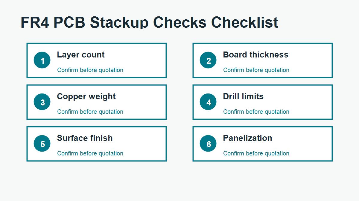
The phrase sounds simple, but a real FR4 printed circuit board includes many manufacturing decisions: layer count, finished thickness, copper weight, drill size, annular ring, solder mask opening, surface finish, impedance requirement, panelization and inspection standard. A good quote should review the whole board package, not only the word FR4.
How FR4 Works Inside the PCB Stackup
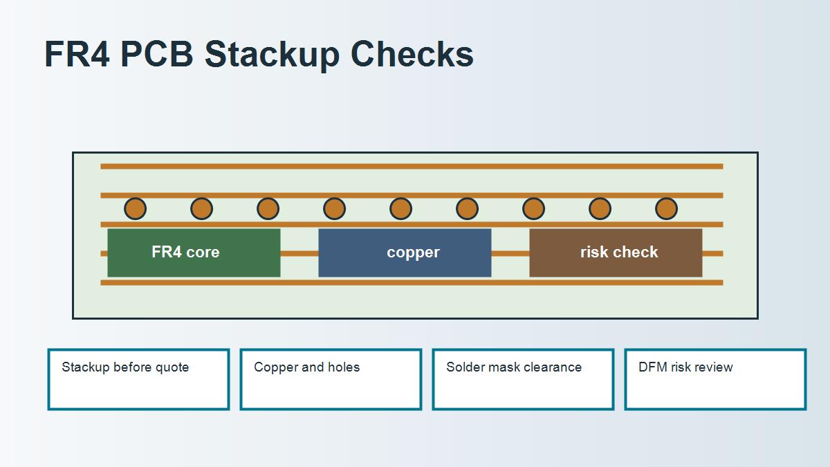
In a single-sided or two-layer board, FR4 may appear as one main insulating sheet with copper on one or both sides. In a multilayer board, FR4 appears as cured cores and prepreg dielectric layers between copper layers. The final performance depends on the whole stackup. Copper thickness changes trace width and current capacity. Dielectric thickness affects impedance. Prepreg flow affects final thickness. Drilling and plating affect via reliability.
This is why a buyer should not approve a board only by looking at the top image or Gerber preview. Ask how the stackup will be built, what material family will be used, what finished thickness tolerance applies and whether the design has any controlled impedance or special reliability requirements.
FR4 PCB Manufacturing Checks
| Check point | What to confirm | Why it matters | Buyer action |
|---|---|---|---|
| Layer count | 1, 2, 4, 6 or more layers | Controls routing, lamination and cost | Send complete Gerber and stackup notes |
| Board thickness | Nominal and tolerance | Affects enclosure fit and impedance | State finished thickness requirement |
| Copper weight | Outer and inner copper | Affects current, etching and cost | Do not leave copper weight ambiguous |
| Minimum drill | Finished hole and aspect ratio | Affects plating reliability | Review small holes before mass production |
| Surface finish | HASL, ENIG, OSP or other finish | Affects solderability, flatness and shelf life | Choose based on components and assembly |
When Standard FR4 Is Enough
Standard FR4 is usually suitable for many control boards, simple digital boards, power management boards, LED driver boards with modest heat, and ordinary multilayer products without severe RF, thermal or reliability stress. If the design is not impedance-critical, not exposed to high operating temperature and not using very demanding hole structures, standard FR4 may be the most practical choice.
Still, “standard” does not mean “no review.” Even a common two-layer board can fail quotation or production if the drill holes are too small for the thickness, copper balance is poor, silkscreen overlaps pads, solder mask dams are too narrow, or the board outline lacks tolerances.
When an FR4 PCB Needs Special Review
| Design situation | Risk | Possible review | Do not assume |
|---|---|---|---|
| Controlled impedance | Trace geometry may not match stackup | Ask for stackup and impedance calculation | Do not copy generic calculator values blindly |
| Lead-free assembly | Thermal stress on laminate and holes | Review Tg, Td, CTE and board thickness | Do not choose only by cheapest FR4 |
| Heavy copper | Etching, spacing and lamination difficulty | Review copper balance and DFM rules | Do not use normal spacing assumptions |
| RF or high frequency | Loss and Dk variation | Consider low-loss material or hybrid stackup | Do not treat FR4 Dk as a fixed number |
Real Manufacturing Case: A Simple FR4 Board That Was Not Simple
A customer requested a quick-turn FR4 printed circuit board for an industrial sensor module. The board was only two layers, so the first assumption was that it would be easy. During DFM review, the factory found narrow solder mask dams between fine-pitch pads, several small plated holes close to board edges and copper pours that made one area much denser than the other.
The material did not need to change. The fix was manufacturing-focused: adjust solder mask openings, increase edge clearance, rebalance copper where possible and confirm the finished board thickness tolerance. The buyer avoided a rushed production run that could have caused solder bridging and edge damage.
Buyer takeaway: an FR4 PCB can be ordinary in material but still risky in fabrication. Always review DFM details before treating a job as a simple board.
FR4 PCB Quote Package Checklist
- Gerber files with all copper, solder mask, silkscreen and outline layers.
- Drill files and slot information.
- Layer count, finished board thickness and copper weight.
- Surface finish, solder mask color and silkscreen color.
- Controlled impedance notes if applicable.
- Panelization request if rails, tabs or V-score are needed.
- Assembly files if PCB assembly is included.
Get an FR4 PCB Manufacturing Review
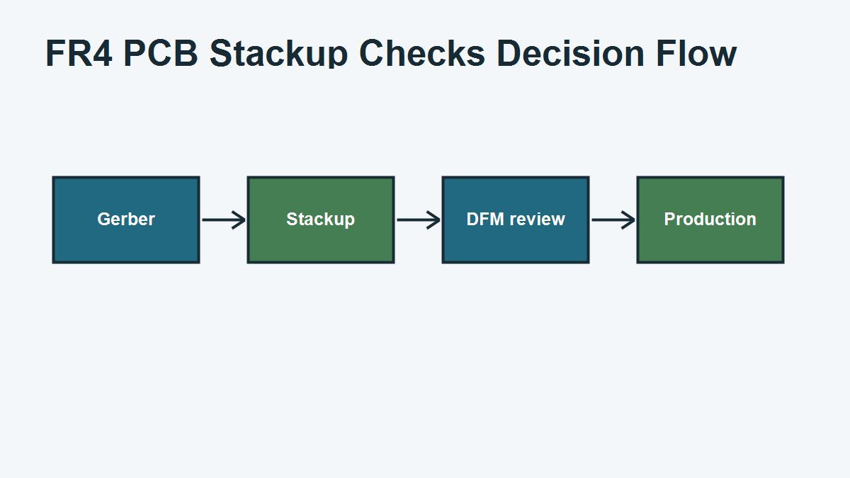
PCBTRY can review FR4 printed circuit board files before production, including stackup, copper weight, drill limits, solder mask, surface finish and DFM risks. If your design uses high frequency signals, heavy copper, tight holes or lead-free assembly, send the complete files and ask for an engineering review before confirming the order.
Common FR4 Mistakes That Cause Quote or Production Problems
The most common FR4 mistake is treating a short material word as a complete production requirement. A PCB supplier cannot reliably quote every risk from the phrase “FR4” alone. The quote also depends on board thickness, layer count, copper weight, surface finish, hole structure, impedance, assembly process, test requirement and delivery quantity. If those details are missing, the first quote may look fast but the order can still change after engineering review.
A second mistake is comparing suppliers only by unit price. One quote may assume standard FR4, loose tolerance and no special report. Another quote may include high-Tg material, impedance coupon, tighter inspection or a controlled stackup. If the assumptions are different, the prices are not truly comparable. Buyers should ask what is included before deciding that one supplier is more expensive.
A third mistake is using a datasheet value without checking how the finished board will be built. Dk, Df, Tg and CTE values are useful, but they must be connected to the actual stackup, copper construction, press process and assembly exposure. For sensitive designs, the better workflow is to share the real files and let the manufacturer confirm a practical build.
Questions to Send With an FR4 PCB RFQ
| Question | Why it helps | What the supplier can confirm |
|---|---|---|
| Is standard FR4 acceptable for this application? | Prevents over-specifying or under-specifying material | Material family, Tg need and substitution rule |
| Can you propose a manufacturable stackup? | Connects material to real production | Core, prepreg, copper and thickness tolerance |
| Does this board need impedance control? | Protects signal integrity requirements | Trace geometry, Dk assumption and coupon options |
| Are there DFM risks in the files? | Finds issues before production | Drill, spacing, annular ring, solder mask and outline risks |
| What should be changed before mass production? | Turns the quote into a decision tool | Cost, yield, testing and reliability improvements |
FR4 FAQ for PCB Buyers
Can I simply write FR4 on the drawing?
You can do that for many simple boards, but it is not enough for every project. If the board has controlled impedance, high assembly temperature, heavy copper, dense vias, RF signals or strict reliability requirements, add the relevant material and stackup notes.
Does higher Tg always mean better FR4?
Higher Tg can improve thermal margin, but it does not automatically solve signal loss, impedance, current carrying or moisture concerns. Match the material upgrade to the actual risk.
Should prototypes and mass production use the same FR4 grade?
For low-risk prototypes, an equivalent stocked FR4 may be acceptable. For controlled or certified products, keep the material rule consistent and document any approved substitution before production.



0 Comments