




How do you open a PCB file?
First identify what the file actually contains, because “PCB file” is not one universal format. A native layout file must usually be opened by its original EDA program or a compatible importer. A Gerber package is manufacturing output and should be opened in a Gerber viewer. An image, PDF, pick-and-place file, or fabrication drawing is supporting data, not an editable board layout.
Work from a copy, keep the original archive unchanged, and inspect before converting. The safe sequence is: identify the extension and source, choose a read-only viewer or matching CAD tool, confirm the layer set and units, then compare the displayed board with the fabrication notes.
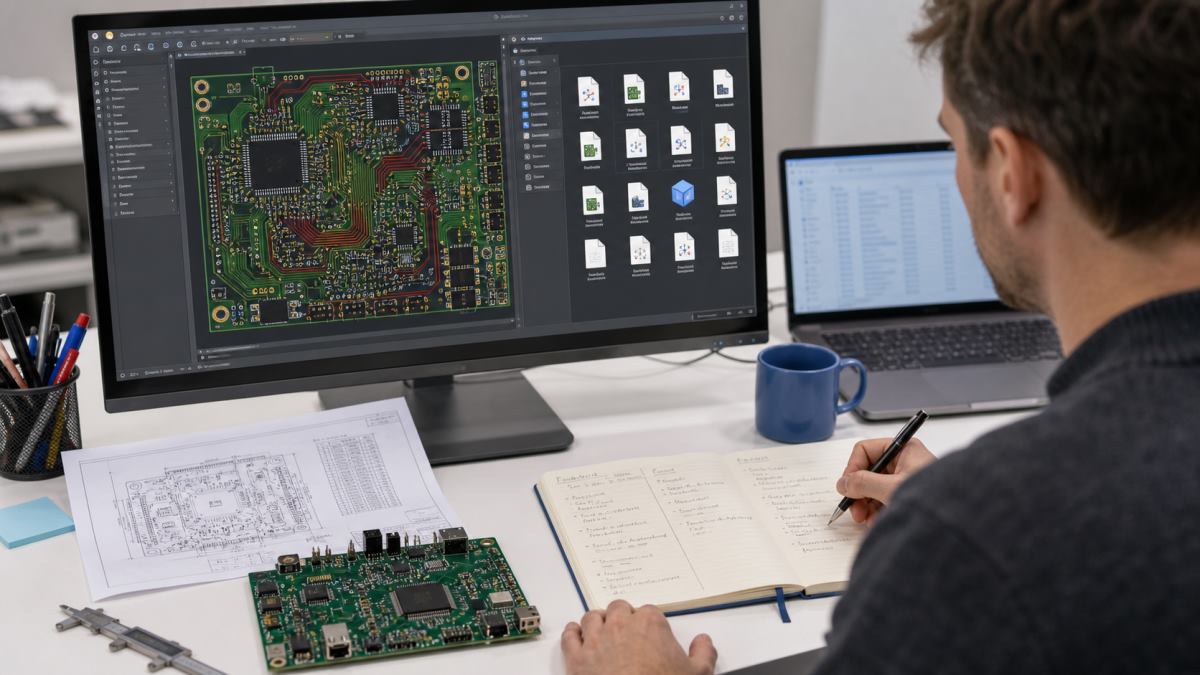
Why the filename extension is only the first clue
Extensions such as .PcbDoc, .kicad_pcb, .brd, and .pcb can point toward a specific tool, but legacy and unrelated programs sometimes reuse the same extension. A file called board.pcb may be text-based, binary, or produced by a discontinued CAD system. Renaming the extension does not convert the data.
Ask who exported it, which software and version they used, and whether the package is source design data or production output. Those three answers are more reliable than guessing from the icon shown by Windows.
Match the PCB file type to the right opening method
| What you received | Typical clues | Best first tool | What to verify |
|---|---|---|---|
| Native PCB layout | .PcbDoc, .kicad_pcb, tool-specific project files | Original EDA software or documented importer | Libraries, stackup, rules, nets, component links |
| Legacy layout | .pcb, .brd, old project archive | Matching legacy reader or controlled translator | Source version, units, layer mapping, lost rules |
| Gerber and drill package | .gbr, .gtl, .gbl, .drl, zipped layers | Gerber/X2 viewer | All copper, mask, legend, outline and drill data |
| ODB++ or IPC-2581 | Structured manufacturing archive | CAM viewer that supports the format | Layer names, net data, drill and profile |
| Drawing or image | PDF, DXF, PNG, JPG | Document or CAD viewer | Reference only; do not treat as fabrication data |
Step 1: preserve the original package
Duplicate the complete folder or ZIP before opening anything. Keep project files, libraries, drill tables, readme notes, and fabrication drawings together. Some CAD packages use relative links, so extracting or moving one file alone can make components, fonts, or models appear missing.
Record the received date and calculate a checksum when revision control matters. If conversion changes a file, save the result under a new name and never overwrite the customer’s source.
Step 2: identify the source without executing unknown content
Check the extension, nearby project files, export notes, and the first readable lines in a plain-text editor. Text headers may reveal a CAD family or format version. If the content is binary or unclear, stop guessing and ask the sender for the software name and version.
Do not install an untrusted executable included in an archive just to view a board. Use a reputable local application or an approved online service, and follow your company’s confidentiality rules before uploading customer design data.
Step 3: decide whether you need to view, edit, or manufacture
A viewer is enough when you only need to inspect shape, layers, apertures, or drills. Editing requires the native tool or a carefully verified import. Manufacturing review is different again: the fabricator needs stable production outputs and specifications, not merely a screenshot of the layout.
- View: choose read-only mode and avoid saving changes.
- Edit: keep a conversion log and compare the imported design with the source.
- Quote or manufacture: provide Gerber/ODB++/IPC-2581, NC drill data, stackup, dimensions, finish, copper weight, impedance and quantity as applicable.
Step 4: open native layouts with a compatible EDA tool
Use the original CAD application when possible. If you must import into another tool, confirm that the importer supports the exact source version. A successful import message does not prove that rules, net classes, pad stacks, fonts, polygons, differential pairs, embedded components, or mechanical layers survived.
Open the project read-only first. Check the board outline and layer count before allowing any library update or rule migration. Then save the converted design as a separate project.
Step 5: open Gerber and drill files as one set
Load the entire fabrication package into one CAM viewer rather than opening each layer in isolation. Align the layers and overlay the drill data. The board outline should form a closed, correctly scaled profile; plated and non-plated holes should appear in the intended locations; solder mask openings should match pads; and top and bottom layers should not be swapped.
A Gerber viewer cannot recover schematic intent or complete design rules. It shows the exported manufacturing geometry, which is exactly why the full set must be checked before release.
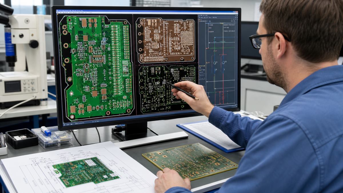
How to tell whether a PCB file opened correctly
| Check | Healthy result | Warning sign | Next action |
|---|---|---|---|
| Board outline | Closed profile at expected dimensions | Multiple outlines, open gaps, wrong scale | Confirm profile layer and units |
| Layer count | Matches stackup/fabrication note | Missing inner copper or duplicated layers | Request complete export |
| Drills | Aligned with pads and mounting features | Offset holes or absent NPTH data | Reload correct drill file and zero origin |
| Text and polarity | Readable legend, correct top/bottom orientation | Mirrored text or inverted negative layer | Review layer side and polarity |
| Units and size | Dimensions agree with drawing | 25.4x scale error or implausible board size | Correct inch/mm interpretation |
| Revision | Filename, drawing and release note agree | Mixed dates or conflicting revision labels | Stop and obtain release confirmation |
What to do when the viewer shows a blank board
A blank canvas usually means the wrong file type, unsupported version, hidden layers, an off-screen origin, or a single empty/support file opened without its companions. Use “zoom to fit,” turn on all imported layers, and check the program’s import log. Confirm the file has a plausible size and was fully extracted from the archive.
If the file is still blank, do not repeatedly resave it. Ask for a fresh export plus a reference PDF or board screenshot so the next attempt has a visual control.
What to do when the scale or holes are wrong
A board that is exactly 25.4 times too large or too small points to an inch/millimeter mismatch. Offset drills often come from a different origin, a mismatched revision, or separate plated and non-plated drill files loaded incorrectly. Compare one known dimension and at least two mounting-hole coordinates before accepting the display.
Do not “fix” manufacturing data by dragging layers into place unless the file owner confirms the intended transform. Request a corrected, synchronized release instead.
Online viewer or local software: which is safer?
Online viewers are convenient for ordinary Gerber checks, but an upload sends design data to a third party. For confidential, export-controlled, medical, defense, or unreleased commercial designs, use an approved local tool and follow the applicable data policy. Review the service’s retention and deletion terms before uploading.
Local software reduces upload exposure but still needs trusted installation media, current security updates, and a controlled conversion process. The choice is a data-handling decision, not only a convenience decision.
PCB file opening and verification checklist
- Keep an untouched copy of the received archive.
- Confirm the source CAD tool and version.
- Separate native design files from manufacturing outputs.
- Use read-only viewing before import or conversion.
- Load the complete Gerber and drill set together.
- Verify outline, dimensions, units, layers, drills, mask and legend.
- Compare filename, drawing and release-note revisions.
- Record any conversion warnings or missing objects.
- Do not upload confidential data without approval.
- Request a corrected release when layers or origins conflict.
What files should you send for PCB manufacturing review?
Send the final fabrication set, NC drill files, board outline, stackup and material requirements, copper weight, surface finish, finished thickness, impedance table where needed, controlled dimensions, quantity, and any special inspection or test notes. For assembly, add the BOM, centroid/CPL file, assembly drawings, polarity notes, firmware or test requirements as applicable.
Native CAD can be useful for engineering clarification, but it should not silently replace an agreed production release. State which package is authoritative.
Frequently asked questions
Can I open every .pcb file with the same program?
No. Multiple programs have used the extension. Identify the source application and version first.
Can I open a PCB file in a text editor?
You may inspect a copy for readable header clues, but a text editor is not a PCB viewer and can corrupt the file if you save it.
Can a Gerber viewer edit the original PCB design?
Generally no. Gerber represents plotted manufacturing geometry and does not contain the complete native design model.
Why are my drill holes offset from the pads?
The drill and Gerber files may use different origins, units, formats, or revisions. Stop and verify the release rather than shifting data by eye.
What does a 25.4 scale error mean?
It commonly indicates that inch data was interpreted as millimeters, or the reverse.
Is it safe to upload PCB files to an online viewer?
Only when the service and upload are allowed by your confidentiality and data-handling requirements.
What if the CAD importer reports success?
Still compare layers, dimensions, nets, pad stacks, polygons, rules, fonts and mechanical data. Success means the import ran, not that nothing changed.
What is the minimum package for a fabrication quote?
At minimum provide viewable fabrication and drill data plus board dimensions, layer count, material/thickness, copper, finish and quantity. More controlled requirements need more documentation.
Request a PCB file and DFM review
If your package opens inconsistently or you are unsure whether it is ready for production, send the original archive, source-tool/version note, fabrication files, drill data, stackup, dimensions and required revision to PCBTRY. Use the PCB manufacturing contact page and state whether you need format identification, DFM feedback, a fabrication quote, or PCBA review.



0 Comments