




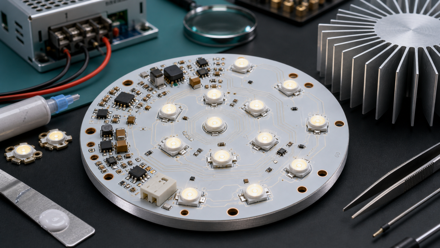
An LED light circuit board is the printed circuit board assembly that holds LED emitters, routes electrical current, supports thermal transfer, and connects the lighting module to a driver or power source. For buyers and engineers, the most important decisions are not only LED brightness and board size, but also current control, heat dissipation, substrate material, optical layout, solder quality, and production testing.
What Is an LED Light Circuit Board?
An LED light circuit board is a PCB or PCBA designed specifically to mount light-emitting diodes and support stable light output. It may be a simple LED array board, a board with resistors and connectors, or a more complete module that includes driver components, dimming control, protection circuits, sensors, and thermal interfaces.
The board has two jobs. Electrically, it delivers controlled current to the LED string or matrix. Mechanically and thermally, it holds LED packages in position and moves heat away from the LED junction. In lighting products, those two jobs are tied together because heat affects brightness, color, and service life.
How an LED Circuit Board Works
An LED circuit board works by routing current through LED emitters while controlling voltage drop, current balance, heat flow, and mechanical alignment. LEDs are current-driven devices, so the board must be designed around current regulation rather than only voltage delivery.
In a basic design, LEDs may be connected in series strings, parallel strings, or a series-parallel network. The board may include resistors, transient voltage protection, connectors, thermistors, or driver ICs. In higher-power lighting, a constant current driver is usually placed on the same board or connected as a separate driver module.
Main Types of LED Light Circuit Boards
LED light circuit boards are usually classified by substrate material, power level, shape, and driver integration. The right type depends on heat load, product size, brightness target, cost, installation environment, and production volume.
| Type | Typical Use | Strength | Limitation |
|---|---|---|---|
| FR-4 LED PCB | Low-power indicators, decorative lighting, control boards | Cost-effective, familiar manufacturing process | Limited heat transfer for high-power LEDs |
| Aluminum MCPCB | Downlights, street lights, grow lights, automotive lighting, light engines | Good thermal transfer and strong mechanical support | Less routing flexibility than multilayer FR-4 |
| Ceramic LED PCB | High-power modules, compact thermal designs, harsh environments | Excellent thermal performance and dimensional stability | Higher cost and stricter processing requirements |
| Flexible LED PCB | LED strips, curved lighting, signs, cabinet lighting | Can bend and fit tight shapes | Thermal performance and current capacity need careful control |
LED PCB Materials: FR-4, Aluminum, Ceramic, and Flexible Circuits
The PCB material should be chosen based on thermal load first, then cost, form factor, and assembly process. Standard FR-4 works for lower-power boards, while aluminum-core PCB and ceramic PCB are common when the LED module must move heat away quickly.
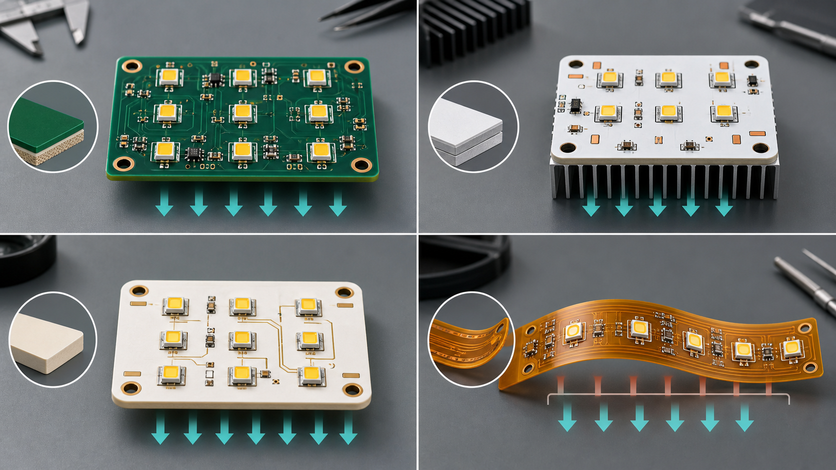
An aluminum metal-core PCB, often called MCPCB, typically uses a metal base, dielectric layer, and copper circuit layer. The dielectric layer is critical because it must provide electrical insulation while allowing heat to move into the metal base. Ceramic boards can provide strong thermal performance in compact or high-reliability designs, but they require careful cost and manufacturability review.
Thermal Management Is the Core Design Issue
Thermal management is usually the most important engineering issue in LED light circuit board design because LED lifetime and color stability are strongly affected by heat. A board that passes electrical testing can still fail as a lighting product if junction temperature rises too high in real use.
- Use a substrate with suitable thermal conductivity for the LED power level.
- Keep the heat path short from LED package to copper pad, dielectric, metal core, thermal pad, heat sink, or housing.
- Check copper area, solder pad size, thermal vias where appropriate, and heat sink contact area.
- Validate the complete assembly, not only the bare board, because enclosure airflow and mounting pressure matter.
- Confirm thermal interface material thickness, coverage, and compression in sample builds.
Constant Current Driver and Circuit Design
LED circuit design should control current accurately because LED brightness and reliability depend on current more than voltage alone. For many lighting products, the LED PCB connects to a constant current driver; in compact modules, driver components may be integrated on the board.
Driver decisions affect safety, dimming, flicker, efficiency, electromagnetic compatibility, heat, and board space. Engineers should define input voltage, LED forward voltage range, current per string, dimming method, protection requirements, connector rating, and whether the driver is isolated or non-isolated. If the driver is off-board, the PCB still needs correct connector layout, polarity protection, and adequate copper width for current.
Design Rules Buyers Should Confirm
Buyers should confirm design rules early because LED boards combine electrical layout, optical spacing, and thermal requirements. A small layout decision can change brightness uniformity, heat behavior, or assembly yield.
| Design Item | What to Define | Why It Matters |
|---|---|---|
| LED spacing | Emitter pitch, lens position, diffuser distance | Affects light uniformity and hot spots |
| Copper thickness | Current path and thermal spreading requirement | Controls voltage drop and heat spreading |
| Solder pad design | Package footprint, thermal pad, paste opening | Reduces solder voids, tilt, and weak joints |
| Connector position | Input/output direction, strain relief, polarity | Prevents installation and wiring failures |
| Mounting holes | Hole size, isolation clearance, heat sink interface | Controls mechanical fit and thermal contact |
Manufacturing Process for LED Light Circuit Boards
The manufacturing process depends on whether the product is a bare LED PCB, assembled LED module, or full lighting PCBA. For metal-core LED boards, the supplier must control the metal substrate, dielectric layer, copper circuit, surface finish, solder mask, LED assembly, and thermal interface requirements.
- Review Gerber files, stack-up, LED footprints, thermal requirements, and assembly drawing.
- Fabricate the PCB using the approved substrate, copper thickness, surface finish, solder mask, and board outline.
- Inspect bare boards for dimensional accuracy, solder mask quality, copper defects, and electrical continuity.
- Assemble LEDs, resistors, connectors, driver components, and protection devices using controlled soldering profiles.
- Test electrical function, polarity, current draw, brightness, color consistency, and thermal behavior.
- Pack boards with ESD and mechanical protection suitable for LED packages and lenses.
Quality Testing for LED PCB Assemblies
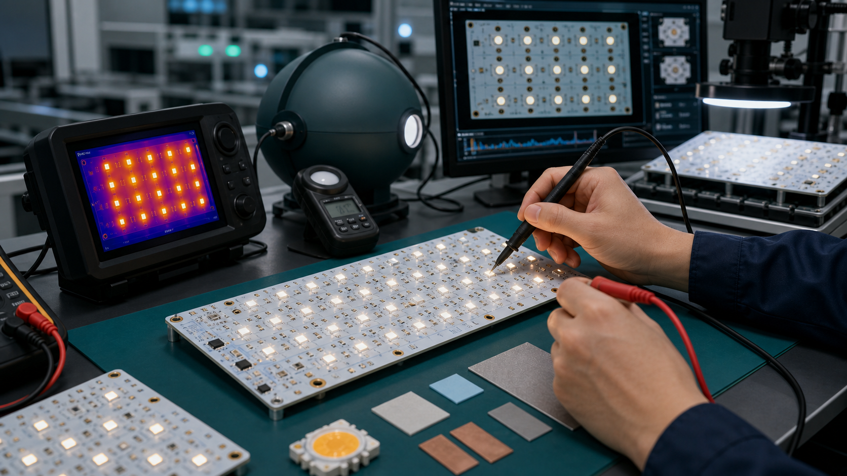
Quality testing should verify light output, electrical stability, solder reliability, and heat performance, not only board continuity. LED products are visible to users, so brightness mismatch, color shift, flicker, and thermal degradation can create complaints even when the circuit technically turns on.
- Incoming LED bin verification for color temperature, brightness, and forward voltage requirements.
- AOI or visual inspection for LED polarity, solder joints, tombstoning, bridging, and missing components.
- Electrical testing for current, voltage drop, open circuits, shorts, and driver function.
- Optical testing for brightness uniformity, color consistency, and visible dark zones.
- Thermal testing at realistic operating current and enclosure conditions.
- Burn-in or aging test when required by product risk, warranty expectation, or customer specification.
Common Failure Modes
Most LED light circuit board failures come from heat, current imbalance, weak soldering, poor material selection, or incomplete validation. A good supplier should help buyers find these risks before mass production.
| Failure Mode | Likely Cause | Prevention |
|---|---|---|
| Brightness drop | High junction temperature or overcurrent | Thermal design review, current control, heat sink validation |
| Color shift | LED bin mismatch, heat stress, aging variation | LED bin control, optical testing, thermal testing |
| Intermittent LED | Weak solder joint, board flex, connector stress | Footprint review, solder profile control, strain relief |
| Hot spot | Poor thermal interface or uneven LED spacing | Thermal pad control, layout optimization, assembly checks |
| Driver overheating | Compact layout, insufficient copper, poor airflow | Driver derating, copper area, enclosure-level thermal test |
Cost Factors in LED Light Circuit Board Production
LED PCB cost is driven by substrate material, board size, copper thickness, LED count, LED binning, surface finish, assembly complexity, test requirements, and production quantity. Choosing the cheapest board can become expensive if it creates heat problems, color inconsistency, or warranty failures.
- Aluminum and ceramic substrates usually cost more than standard FR-4 but may reduce thermal risk.
- Higher-power LEDs require better thermal paths, stronger validation, and sometimes tighter assembly control.
- Consistent color temperature and brightness binning can affect component sourcing and inventory cost.
- Integrated drivers increase assembly complexity but may simplify final product wiring.
- Extra optical, thermal, burn-in, or aging tests add cost but reduce field risk.
Supplier Selection Checklist
The right LED PCB supplier should understand thermal design, LED assembly, optical consistency, and production testing. Ask questions that reveal engineering control, not only price and lead time.
- Can you manufacture FR-4, aluminum MCPCB, ceramic, or flexible LED boards according to the project requirement?
- Can you review the LED thermal path before sample production?
- Can you assemble LEDs with controlled polarity, solder profile, and ESD handling?
- Can you support LED bin control for brightness and color temperature?
- What electrical, optical, and thermal tests can you provide with samples and production lots?
- Can you provide inspection photos, test records, and traceability for critical components?
- How do you handle design changes, material substitutions, and nonconforming LED batches?
Pre-Production Checklist for Buyers
Before ordering LED light circuit board production, buyers should lock the technical requirements and sample acceptance criteria. This prevents the supplier from guessing about power, brightness, heat, and installation details.
- LED type, package, brand or approved equivalent, color temperature, brightness bin, and forward voltage range.
- Input voltage, drive current, LED string design, dimming method, and protection requirements.
- PCB material, copper thickness, surface finish, solder mask, board thickness, and thermal conductivity requirement.
- Heat sink, thermal pad, housing, mounting hole, and installation condition.
- Optical target such as beam angle, diffuser distance, brightness uniformity, and color consistency.
- Sample test plan, aging requirement, packaging requirement, labeling, and production documentation.
FAQ
What is an LED light circuit board?
An LED light circuit board is a PCB assembly that mounts LED emitters and provides electrical paths, current control connections, heat transfer paths, and mechanical support for a lighting product.
What PCB material is best for LED lighting?
Aluminum-core PCB is commonly used for LED lighting because it transfers heat better than standard FR-4. FR-4 can work for low-power LEDs, while ceramic PCB is used for higher thermal performance or demanding reliability requirements.
Why is thermal management important for LED circuit boards?
Thermal management is critical because excessive junction temperature reduces LED brightness, color stability, efficiency, and lifetime. The PCB must transfer heat from the LED package to the substrate, heat sink, housing, or other cooling path.
Does an LED circuit board need a constant current driver?
Most medium- and high-power LED lighting products need constant current control. Some boards integrate driver components, while others connect to an external driver. The right choice depends on power, space, safety, dimming, and reliability requirements.
What is an aluminum MCPCB for LEDs?
An aluminum MCPCB is a metal-core printed circuit board with an aluminum base, insulating dielectric layer, and copper circuit layer. It is widely used for LED modules because it helps move heat away from LED packages.
Can FR-4 be used for LED light boards?
FR-4 can be used for low-power LED boards, indicator lights, decorative lighting, and control circuits. For high-power lighting, FR-4 may not remove heat fast enough unless the design includes a suitable thermal strategy.
What causes LED PCB failure?
Common causes include high operating temperature, overcurrent, poor solder joints, weak thermal interface, LED bin mismatch, connector stress, moisture exposure, and incomplete sample testing before production.
How do you test an LED light circuit board?
Testing usually includes visual inspection, AOI, electrical continuity, current and voltage checks, LED polarity verification, brightness and color checks, thermal testing, and aging or burn-in when required by the application.
What information is needed for an LED PCB quote?
A useful quote package should include Gerber files, BOM, LED specifications, current and voltage requirements, board material, copper thickness, assembly drawing, test requirements, quantity, and sample acceptance criteria.
Is ceramic PCB better than aluminum PCB for LEDs?
Ceramic PCB can provide excellent thermal performance and reliability for demanding LED modules, but it is usually more expensive. Aluminum PCB is often the practical choice for many commercial lighting products.
How does LED binning affect circuit board production?
LED binning groups LEDs by brightness, color temperature, and forward voltage. Tight bin control improves visual consistency but may affect sourcing, lead time, and cost. Buyers should define bin requirements before production.
What should buyers check before ordering LED PCB production?
Buyers should confirm LED power, current, voltage, substrate material, copper thickness, thermal interface, solder mask color, optical requirements, driver design, testing plan, and sample validation before mass production.
Final Takeaway
A reliable LED light circuit board is the result of balanced electrical, thermal, optical, and manufacturing decisions. The best design is not always the most expensive board; it is the board that keeps current stable, moves heat effectively, supports consistent light output, and can be produced with repeatable quality.
If you’re sourcing reliable PCB/PCBA manufacturing, including OEM, ODM, prototyping, mass production, or custom engineering solutions, reach out to our engineering team for technical support and a quote at [email protected].



0 Comments