




Why PCB FR4 Material Selection Matters
PCB FR4 material is often treated as a default choice, but default does not mean careless. The material affects insulation, mechanical strength, thermal behavior, impedance, soldering reliability and long-term board performance. A buyer who only writes “FR4” may still receive a board that works for a simple prototype but is not ideal for lead-free assembly, high-speed routing or a harsh environment.
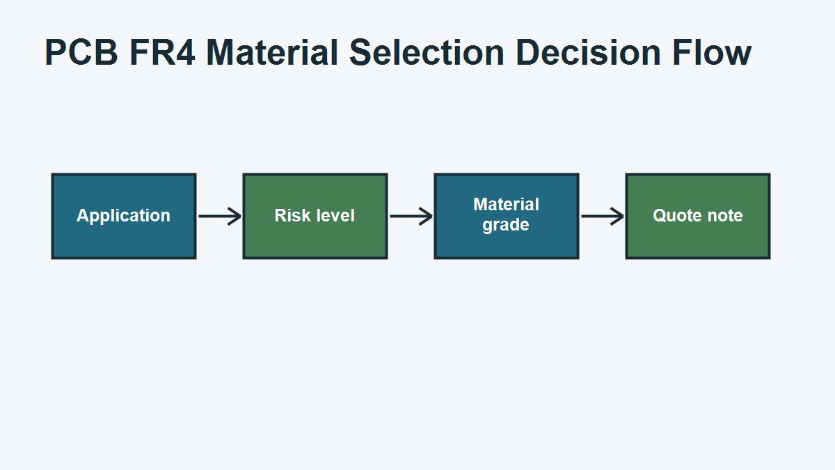
The right question is not “Is FR4 good?” The better question is “Which FR4 material condition is good enough for this board?” A low-speed control board, a dense four-layer industrial PCB, a high-current board and a high-frequency module may all use FR4 in some form, but they do not need the same review depth.
PCB FR4 Material Selection Matrix
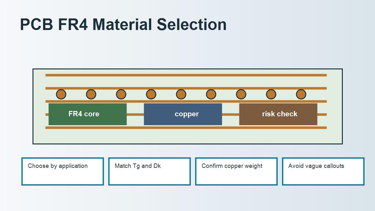
| Design risk | FR4 property to review | Why it matters | Buyer instruction |
|---|---|---|---|
| Lead-free soldering | Tg, Td and CTE | Thermal stress can affect holes and laminate | State assembly profile and reliability need |
| Controlled impedance | Dk and dielectric thickness | Stackup controls trace geometry | Ask for manufacturable stackup |
| Higher frequency | Dk, Df and copper roughness | Loss and phase behavior become important | Confirm whether standard FR4 is acceptable |
| High current | Copper weight and heat path | Temperature rise and spacing drive design | Share current load and copper requirement |
| Mechanical fit | Finished thickness tolerance | Board must fit connectors and enclosure | Specify finished tolerance, not only nominal value |
Standard FR4 vs High-Tg FR4 vs Low-Loss Material
| Option | Best use | Strength | Limit | When to choose |
|---|---|---|---|---|
| Standard FR4 | General rigid boards | Low cost and easy availability | Limited thermal and RF margin | Normal applications without severe risk |
| High-Tg FR4 | Higher thermal stress and lead-free assembly | Better thermal margin | Not automatically low-loss | Dense, thick or reliability-sensitive boards |
| Low-loss laminate | RF and high-speed routing | Lower dielectric loss and better control | Higher cost and tighter stackup control | When signal loss budget demands it |
This table prevents a common purchasing mistake: using a premium material name without knowing the real failure mode. High-Tg helps thermal reliability. Low-loss material helps signal loss. Heavy copper helps current but also changes etching and spacing. Each upgrade should solve a defined problem.
What to Put on the Drawing or RFQ
A useful PCB material instruction is specific enough for the factory to quote correctly but flexible enough to allow manufacturable alternatives when the design permits. For ordinary boards, you may specify FR4, layer count, board thickness, copper weight, surface finish and assembly requirements. For sensitive boards, add Tg requirement, impedance target, material family, allowed substitution rules and testing needs.
Do not bury critical material requirements only in email text. If the requirement affects price or reliability, include it in the drawing, stackup note or RFQ package. This reduces misunderstanding when the job moves from quotation to engineering to production.
Real Procurement Case: The Cheapest FR4 Quote Was Not the Safest Quote
A buyer compared two quotes for a four-layer controller board. One supplier quoted standard FR4 with no stackup detail. Another supplier asked about assembly profile, copper weight and operating temperature, then recommended high-Tg FR4 and a clearer stackup. The second quote was slightly higher, but it explained the risk: the board had many plated holes, lead-free assembly and limited thermal margin.
The buyer originally thought the second supplier was upselling. After reviewing the application, the engineering team agreed that the extra material review was justified. The final order used the high-Tg option for production and kept standard FR4 only for an early non-critical prototype.
Buyer takeaway: a lower FR4 price is not automatically better. Compare what each quote assumes about material grade, stackup, copper, testing and assembly risk.
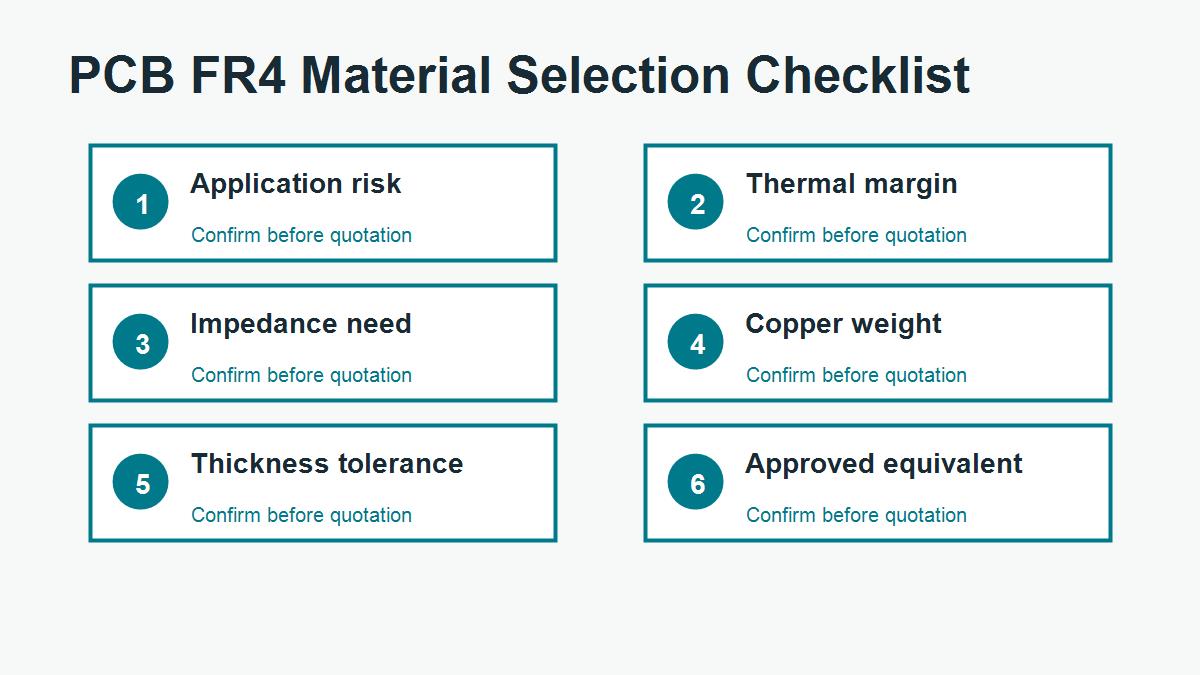
FR4 Material Checklist for PCB Buyers
- What product environment will the board face?
- Is lead-free reflow or repeated rework expected?
- Does the board need controlled impedance?
- Are there RF, high-speed or long trace length concerns?
- What copper weight is required on each layer?
- What finished board thickness and tolerance are needed?
- Can the factory substitute an equivalent FR4 grade?
- Does the order need a material certificate or test report?
Related Material Guides
If you are still defining the material family, start with what FR4 means. If the main issue is electrical performance, read the FR4 dielectric constant guide. For supplier data review, use the FR4 datasheet checklist.
Ask PCBTRY Before Locking the Material
Send PCBTRY your Gerber files, stackup, copper weight, board thickness, impedance notes, assembly process and operating environment. PCBTRY can help confirm whether standard FR4 is enough, whether high-Tg FR4 is needed, or whether another material route should be reviewed before quotation.
Common FR4 Mistakes That Cause Quote or Production Problems
The most common FR4 mistake is treating a short material word as a complete production requirement. A PCB supplier cannot reliably quote every risk from the phrase “FR4” alone. The quote also depends on board thickness, layer count, copper weight, surface finish, hole structure, impedance, assembly process, test requirement and delivery quantity. If those details are missing, the first quote may look fast but the order can still change after engineering review.
A second mistake is comparing suppliers only by unit price. One quote may assume standard FR4, loose tolerance and no special report. Another quote may include high-Tg material, impedance coupon, tighter inspection or a controlled stackup. If the assumptions are different, the prices are not truly comparable. Buyers should ask what is included before deciding that one supplier is more expensive.
A third mistake is using a datasheet value without checking how the finished board will be built. Dk, Df, Tg and CTE values are useful, but they must be connected to the actual stackup, copper construction, press process and assembly exposure. For sensitive designs, the better workflow is to share the real files and let the manufacturer confirm a practical build.
Questions to Send With an FR4 PCB RFQ
| Question | Why it helps | What the supplier can confirm |
|---|---|---|
| Is standard FR4 acceptable for this application? | Prevents over-specifying or under-specifying material | Material family, Tg need and substitution rule |
| Can you propose a manufacturable stackup? | Connects material to real production | Core, prepreg, copper and thickness tolerance |
| Does this board need impedance control? | Protects signal integrity requirements | Trace geometry, Dk assumption and coupon options |
| Are there DFM risks in the files? | Finds issues before production | Drill, spacing, annular ring, solder mask and outline risks |
| What should be changed before mass production? | Turns the quote into a decision tool | Cost, yield, testing and reliability improvements |
FR4 FAQ for PCB Buyers
Can I simply write FR4 on the drawing?
You can do that for many simple boards, but it is not enough for every project. If the board has controlled impedance, high assembly temperature, heavy copper, dense vias, RF signals or strict reliability requirements, add the relevant material and stackup notes.
Does higher Tg always mean better FR4?
Higher Tg can improve thermal margin, but it does not automatically solve signal loss, impedance, current carrying or moisture concerns. Match the material upgrade to the actual risk.
Should prototypes and mass production use the same FR4 grade?
For low-risk prototypes, an equivalent stocked FR4 may be acceptable. For controlled or certified products, keep the material rule consistent and document any approved substitution before production.



0 Comments