




How to Identify PCB Components Safely and Accurately
Identifying a part on a printed circuit board is not the same as making a quick visual guess. A black three-pin package may be a transistor, MOSFET, regulator, or another device; a short SMD code may be shared by several parts. The reliable approach is to collect clues in a sequence, then confirm the result with the board documentation whenever possible.
This guide explains how to identify PCB components for inspection, troubleshooting, repair documentation, or assembly review. It helps you classify common parts, understand board markings, and know when an exact identification needs a BOM, schematic, datasheet, or qualified technician.
Start With Safety and the Board’s Documentation
Before touching the board, disconnect it from mains power, batteries, and external power supplies. Some equipment contains capacitors that can retain hazardous energy after it is unplugged. Do not probe a powered board unless you are trained, have the correct insulated equipment, and understand the circuit’s hazards.
Gather the evidence already associated with the PCB: the assembly drawing, bill of materials (BOM), schematic, board revision, product model, and any service documentation. These records are more reliable than appearance. Take clear photos of both sides before removing a part, and record its board location, for example C17 or U4.
Read Reference Designators and Silkscreen First
The printed labels on the PCB are called silkscreen markings. A reference designator usually combines a letter with a number and connects a physical location to the schematic and BOM. Common conventions include:
| Marking | Usually indicates | What to verify next |
|---|---|---|
| R | Resistor | Value code, BOM, schematic value |
| C | Capacitor | Capacitance, voltage rating, polarity |
| L | Inductor or ferrite bead | Value, current rating, circuit location |
| D | Diode, LED, or TVS device | Part marking, polarity, voltage/current rating |
| Q | Transistor or MOSFET | Package, pinout, part number, ratings |
| U | Integrated circuit | Top mark, package, datasheet, pin 1 |
| J / CN | Connector | Pin count, keying, signal assignment |
| F | Fuse or resettable fuse | Current, voltage, breaking characteristics |
Conventions can vary, so treat the designator as a strong category clue rather than final proof. Match the exact identifier against the BOM or schematic when they are available.
Identify Components by Package, Pins, and Physical Clues
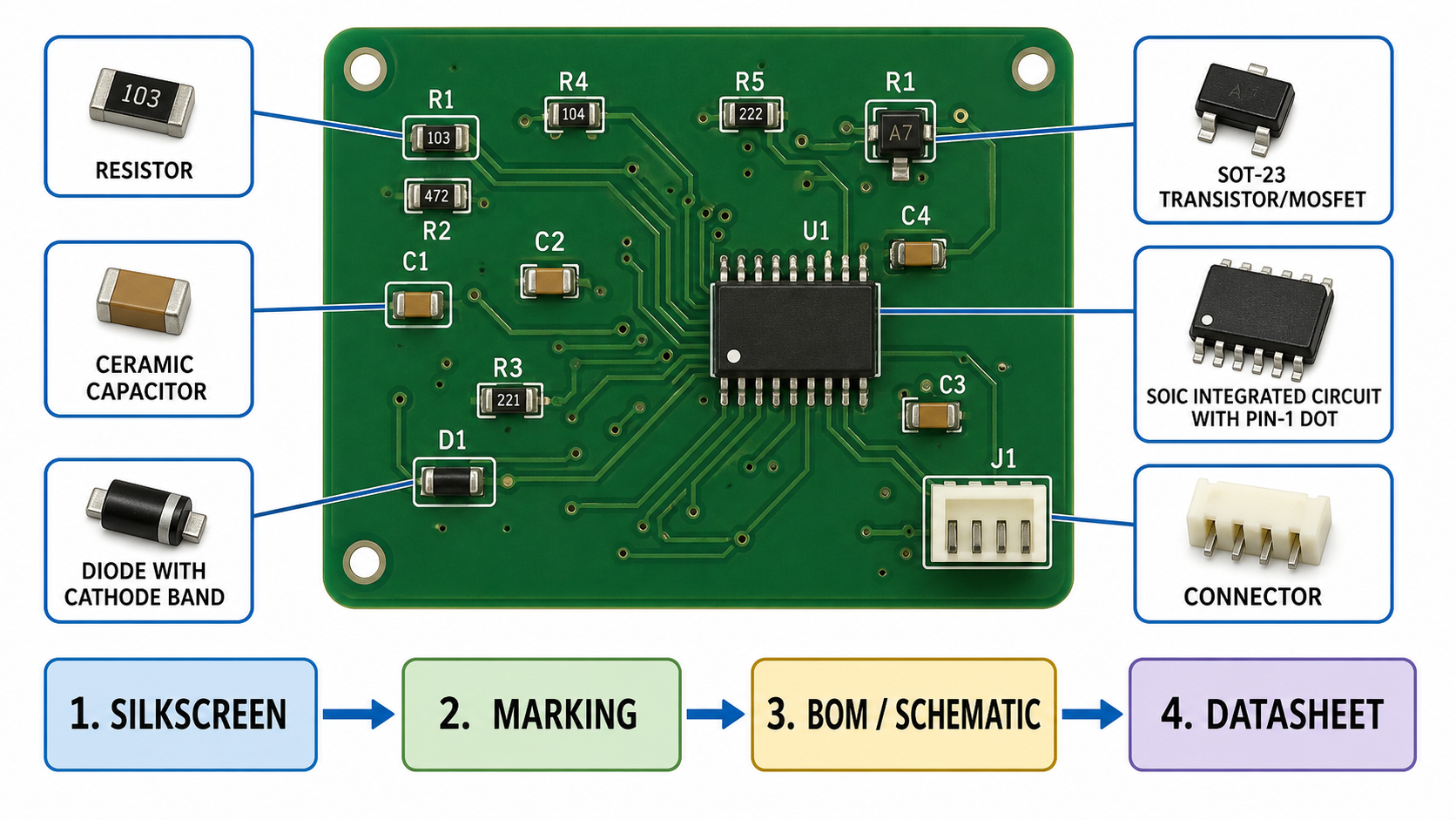
Start with the broad component family. Resistors are often small rectangular SMD chips or axial leaded parts with color bands. Ceramic capacitors are usually unmarked tan, brown, or gray chips, while electrolytic capacitors are commonly cylindrical and carry a polarity stripe. Inductors may be wound coils, shielded blocks, or larger molded SMD parts.
Diodes often have a band that marks the cathode. LEDs may have a package mark, a different pad shape, or a silkscreen polarity symbol. ICs come in many packages—SOIC, QFN, QFP, BGA, and more—and their pin count and package dimensions narrow the search. Connectors, switches, relays, crystals, fuses, and transformers are often easier to classify by shape, mounting style, and surrounding circuit.
Physical clues are only the first layer. For a broader visual introduction, see PCBtry’s existing PCB component identification guide, then use the confirmation steps below before ordering a replacement.
Use Part Markings Without Treating Them as Proof
Read every visible marking with magnification and good lighting. For a resistor, a three- or four-digit code may identify its resistance; very small precision resistors may use EIA-96-style codes. A capacitor may show a value or voltage code, but many multilayer ceramic capacitors have no readable top marking. ICs and transistors often have short top marks instead of a complete manufacturer part number.
Top marks are not globally unique. A code can be reused by different manufacturers, in different packages, or across different date and lot markings. Search results that match only one short code should be treated as candidates. Confirm the package dimensions, pin count, pinout, board function, and electrical ratings before accepting a candidate.
Confirm Identity With the BOM, Schematic, and Datasheet
For an exact answer, use the evidence in this order:
- Match the reference designator to the BOM.
- Match that identifier to the schematic and note its function in the circuit.
- Compare the footprint, package, pin count, and orientation on the board.
- Check the manufacturer datasheet for pinout, absolute maximum ratings, and recommended footprint.
- Confirm any substitute part against voltage, current, power, tolerance, temperature, and functional requirements.
This sequence separates a likely category from a verified part number. It also prevents a common repair mistake: replacing a component that fits the pads but has the wrong pinout, polarity, tolerance, or voltage rating.
Check Polarity, Pin 1, Ratings, and Footprint Before Replacement
Polarity and orientation errors can damage a board immediately. Look for diode bands, electrolytic-capacitor negative stripes, + symbols, LED marks, IC dots or notches for pin 1, and pin-1 indicators on the silkscreen. Compare them to the original documentation, not only to an online photo.
A replacement must also match the footprint and its electrical requirements. Two parts can share an SOT-23 or SOIC footprint while having different pin assignments. A physically similar capacitor can have an unsuitable voltage rating; a similar fuse can have a different time-current response. If one required parameter cannot be confirmed, pause the replacement process.
Use a Multimeter Only When It Can Safely Add Evidence
A multimeter can support identification, but in-circuit readings can be misleading because parallel components change the measurement. With the board safely disconnected and discharged, resistance mode can help locate obvious resistors or shorts, continuity can trace simple connections, and diode mode can sometimes help verify diode junction behavior.
Do not use a meter result as a universal identification method. For example, a diode-mode reading may be affected by connected semiconductors, and capacitance readings may be inaccurate in circuit. Follow the manufacturer’s service documentation and remove or isolate a part only when you are qualified to do so.
Common PCB Components: Identification Clues and Limits
| Component | First clues | What confirms it |
|---|---|---|
| Resistor | R designator, rectangular chip, color bands or value code |
BOM value and power rating |
| Capacitor | C designator, ceramic chip or cylindrical can |
BOM, capacitance, voltage, polarity |
| Inductor | L designator, coil or molded magnetic body |
Inductance/current specification |
| Diode / LED | D designator, cathode band or polarity mark |
Datasheet, circuit role, ratings |
| Transistor / MOSFET | Q designator, three or more pins |
Exact pinout and ratings from datasheet |
| IC | U designator, multi-pin package, top mark |
BOM plus package/pinout match |
| Connector | J or CN designator, keyed housing or header |
Schematic signal names and mechanical drawing |
| Fuse | F designator, marked link or cartridge/SMD body |
Current, voltage, and speed rating |
A Practical PCB Component Identification Checklist
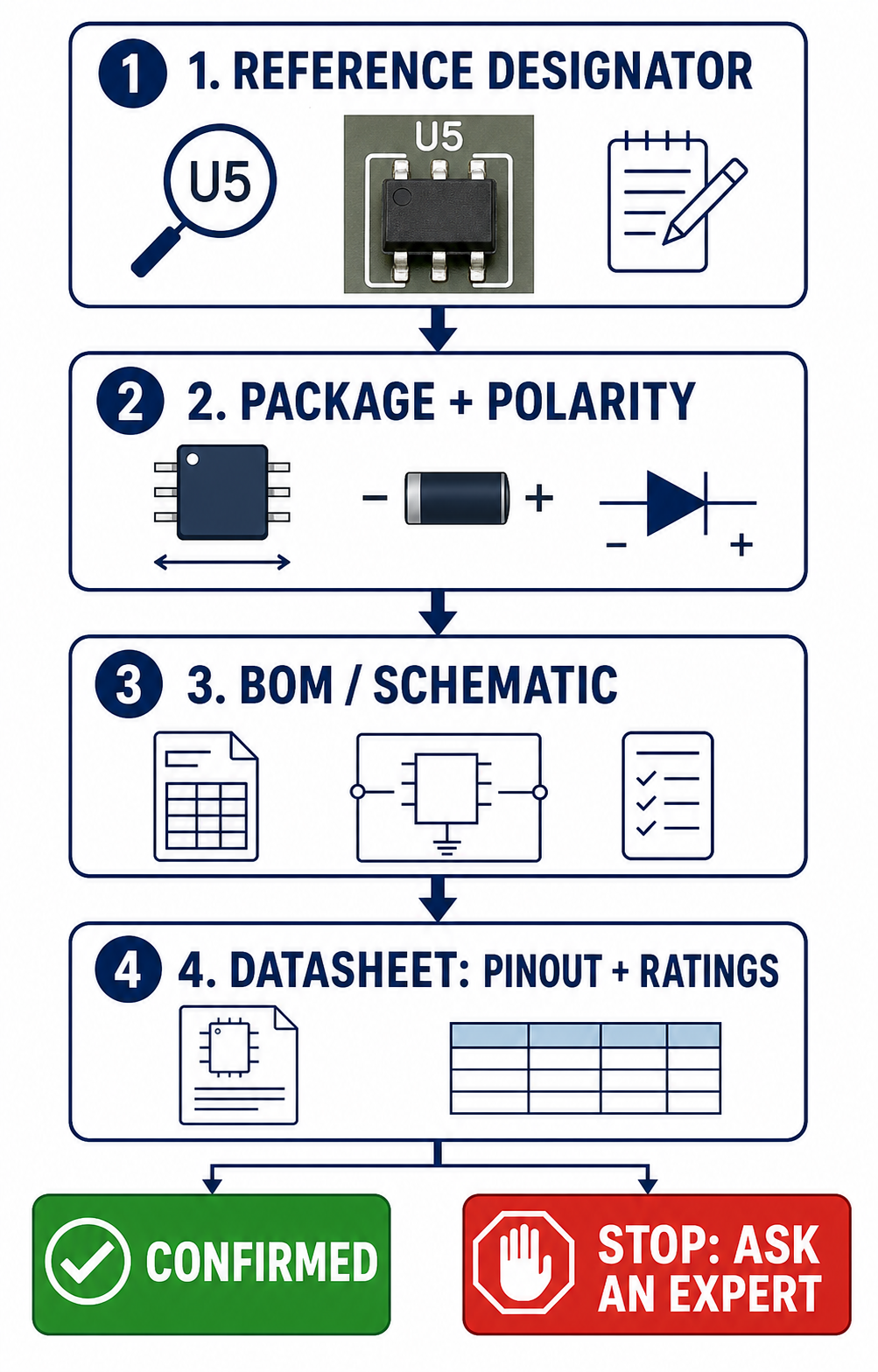
Use this checklist for every unknown part:
- Make the board safe and photograph both sides.
- Record the reference designator and all readable markings.
- Identify the likely component family from designator, package, pins, and nearby circuitry.
- Search the BOM and schematic for that exact designator.
- Match the candidate datasheet to the package, footprint, pinout, and rating.
- Verify orientation and polarity before any removal or replacement.
- Treat in-circuit testing as supporting evidence, not final proof.
- Stop and seek qualified help when documentation, ratings, or circuit function remain uncertain.
Engineering Scenario: Verifying a Failed Power-Input Part
Consider a repair technician examining an unpowered 24 V controller with a damaged three-pin SMD part beside the input connector. The board label reads Q3, the package resembles SOT-23, and the top mark is partly erased. Calling it a MOSFET from appearance alone would be unsafe: an SOT-23 footprint can also carry a BJT, a small regulator, or another device.
Problem manifestation
The damaged device has an ambiguous package and an incomplete top mark. A replacement selected only by footprint could fit the pads but have an incompatible pinout or rating.
Handling method
The technician records the board revision and Q3 location, finds Q3 in the BOM, and checks the schematic. The schematic shows that it is a reverse-polarity protection P-channel MOSFET. The datasheet is then compared with the footprint for pin order, drain-source voltage, current, on-resistance, and gate rating. Only after those checks can a replacement candidate be evaluated.
Reader takeaway
This workflow prevents a mechanically fitting but electrically incompatible part from being installed. It also shows why visual recognition starts an identification process but does not complete it.
For teams preparing a board for assembly or documentation, PCBtry can help turn validated design data into a manufacturable PCB and assembly process. Visit PCBtry when you are ready to discuss a production-ready design.
When an Unknown Component Requires Expert Help
Escalate when the board is mains-powered, damaged by heat or liquid, uses high-voltage or high-current circuits, has missing documentation, or contains BGA, QFN, or other parts that cannot be safely inspected or replaced with basic tools. An engineer or qualified repair professional can compare circuit behavior with the schematic, use appropriate instruments, and determine whether a replacement is safe.
Frequently Asked Questions
What is the easiest way to identify PCB components?
Begin with the reference designator and silkscreen, then compare the physical package and any body markings with the BOM and schematic. The BOM or schematic is the strongest confirmation for an exact part.
How do I identify a resistor on a PCB?
Look for an R designator and a rectangular SMD part or an axial part with color bands. Confirm its resistance and power rating from the BOM or its printed code where applicable.
How can I tell a capacitor from a resistor on a circuit board?
Use the reference designator first: C normally identifies a capacitor and R a resistor. Ceramic capacitors are often unmarked, so visual appearance alone is not enough for an exact value.
What do R, C, D, Q, and U mean on a PCB?
They are common reference-designator prefixes: resistor, capacitor, diode, transistor/MOSFET, and integrated circuit. They guide identification but should be checked against the board documentation.
Can I identify an IC from its top marking?
Sometimes, but a short IC top mark is often not unique. Verify the package, pin count, footprint, circuit location, and datasheet before deciding on the exact part number.
How do I identify diode polarity on a PCB?
Look for a band on the diode body and a corresponding bar or polarity mark on the silkscreen. Confirm the orientation in the schematic or assembly drawing before replacement.
Can a multimeter identify an unknown PCB component?
A multimeter can provide supporting clues for a safely disconnected and discharged board, but in-circuit readings can be affected by other parts. It cannot by itself reliably identify every unknown component.
How do I identify SMD components with no markings?
Use the reference designator, footprint, board location, nearby circuit, BOM, schematic, and design files. An unmarked ceramic capacitor or small package cannot be reliably identified by appearance alone.
Is it safe to replace a component with one that has the same package?
No. The replacement must also match the pinout, polarity, voltage, current, power, tolerance, and circuit function. Same-package parts can be electrically incompatible.
What should I do if I cannot identify a PCB component?
Do not guess or substitute a part. Preserve the board, collect clear photographs and markings, locate the original documentation, and ask a qualified engineer or repair professional for help.
0 Comments