




How can you mount a PCB without holes?
Support the board at its edges or approved keepout areas using enclosure rails, snap clips, card guides or adhesive-backed standoffs. Direct bonding can work for light, low-service assemblies, but the adhesive must match temperature, vibration, surface and lifetime requirements. Never clamp components or rely on solder joints to carry mechanical loads.
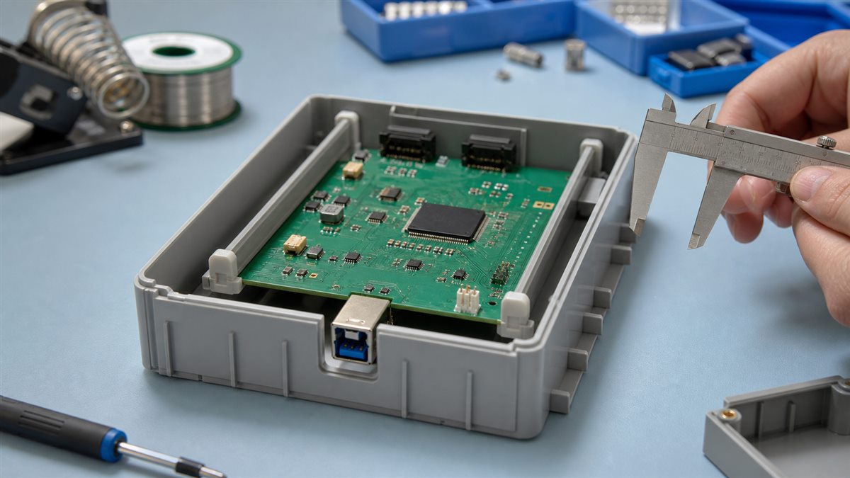
Choose a no-hole mounting method
| Method | Best fit | Advantage | Main risk |
|---|---|---|---|
| Molded rails/card guides | Purpose-designed enclosure | Repeatable and serviceable | Wrong board thickness or loose tolerance |
| Edge snap clips | Tool-free assembly | Fast installation | Local edge stress |
| Adhesive standoffs | Flat clean housing | Maintains underside clearance | Adhesive aging or peel |
| Structural bonding | Low-service sealed unit | Few parts | Difficult rework and unknown stress |
| Retaining frame | Irregular or valuable board | Distributes load | Custom enclosure space |
Map loads before selecting hardware
Mark gravity, shock, vibration, cable pull and connector insertion directions. USB, terminal blocks and antennas can apply more local force than board weight. Transfer those loads into the enclosure near the connector instead of bending the PCB across its width.
Protect electrical clearance and insulation
Maintain the required spacing below solder joints, leads and high-voltage nets. Use insulating supports with appropriate material ratings and keep metal clips away from exposed copper. Check that adhesive cannot flow onto contacts and that foam does not trap heat around power parts.
Use rails and card guides
Rails are the cleanest option when enclosure geometry can be changed. Match groove width to finished PCB thickness and tolerance, provide an insertion lead-in and add an end stop so the board cannot slide into a connector wall. Allow controlled clearance rather than forcing a bowed board into undersized grooves.
Use snap clips without cracking the board
Place clips on component-free edge zones and distribute them so removal does not twist the laminate. The clip should retain the board without scraping copper or solder mask. Validate installation and removal over the expected service cycles.
Use adhesive-backed standoffs correctly
- Confirm enclosure and adhesive material compatibility.
- Clean both surfaces using the adhesive supplier’s process.
- Locate supports under mechanically quiet board areas.
- Apply specified pressure and cure/dwell time.
- Pull in the intended load direction only after cure.
- Test hot, cold, humidity and vibration conditions relevant to the product.
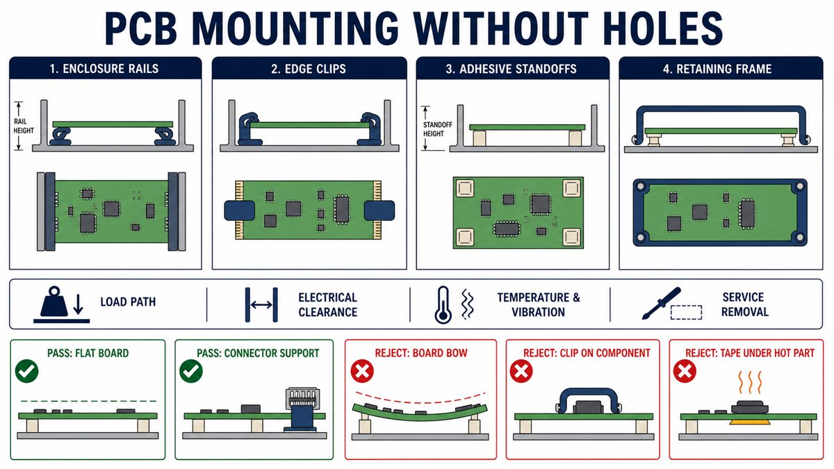
Be cautious with foam tape, hot glue and potting
These methods may suit a quick indoor prototype, but they are not automatically production solutions. Foam tape can creep, hot glue can soften, and potting can load components during cure or thermal cycling. Check flammability, temperature, outgassing, chemical compatibility and repair strategy.
Inspect the mounted PCB
| Check | Pass | Reject |
|---|---|---|
| Board shape | Flat and unstressed | Visible bow or twist |
| Retention | No movement under defined load | Rattle, creep or clip release |
| Clearance | No contact below components | Support touches leads or pads |
| Connectors | Housing carries insertion load | PCB flexes during mating |
| Service | Removal method is controlled | Board must be pried near parts |
When to redesign the PCB or enclosure
Add proper mounting holes or mechanical keepouts when shock, repeated service, heavy cables or compliance testing makes improvised retention risky. A small board revision is often cheaper than field failures or a difficult assembly fixture.
Mechanical handoff for manufacturing
Provide the board outline, finished thickness, component height map, keepouts, connector datum, enclosure model, retention parts and assembly sequence. Confirm that fabrication data matches the mechanical model before release.
No-hole mounting checklist
- Loads and connector forces are mapped.
- Supports touch only approved board areas.
- Electrical clearance and insulation are maintained.
- Board remains flat after installation.
- Adhesive is validated for surface and environment.
- Heat-producing parts retain airflow.
- Removal does not pry against components.
- Shock, vibration and mating tests match product use.
Frequently asked questions
Can I use double-sided tape under a PCB?
Only when the tape is rated for the surfaces, temperature and load, and sufficient electrical clearance remains below the board.
Is hot glue safe for mounting a PCB?
It can hold a light prototype, but temperature, flammability, contamination and serviceability must be evaluated before production use.
Can a PCB slide directly into enclosure rails?
Yes, when groove width, finished board thickness, tolerance, insertion force and end retention are designed together.
Where should clips touch the PCB?
Use component-free edge keepouts without exposed copper, fine traces or fragile castellations.
How do I stop connector insertion from flexing the PCB?
Support the enclosure close to the connector or add a connector-specific bracket so mating force bypasses the board span.
Can foam support touch components?
Avoid it unless material, pressure, temperature and component compatibility are explicitly qualified.
Are adhesive standoffs removable?
The PCB may release from the snap feature, but the adhesive base may not be reusable. Define a service procedure.
Should I add holes in the next revision?
Add them when predictable fastener load, grounding, repeated access or compliance testing outweighs the board-area cost.
What mechanical files should I send a PCB supplier?
Send board outline and thickness, drill/Gerber data, component height and keepout information, enclosure CAD and mounting requirements.
Request a PCB mechanical review
Send the Gerber and drill files, board thickness, enclosure model, connector loads, keepouts, quantity and environmental requirements through the PCBtry contact page for a manufacturing and mechanical-fit review.



0 Comments