




PCB manufacturing process machines convert released design data and copper-clad laminate into tested bare boards through imaging, etching, lamination, drilling, plating, solder-mask, profiling, and inspection operations. No single machine “makes a PCB.” Product capability comes from the complete route, process chemistry, tooling, measurement system, maintenance, utilities, trained operators, and engineering controls working together.
Engineers and buyers should therefore evaluate the output a machine must control rather than compare model names or maximum speeds. Send your Gerbers, drill and outline files, stack-up, materials, quantities, tolerances, and test requirements through PCBTRY’s contact page for a route and DFM review.

What Machines Are Used in PCB Manufacturing?
The equipment set follows the chosen board technology. A simple two-layer rigid board uses fewer operations than a multilayer, HDI, flex, heavy-copper, or special-material construction. The table maps major equipment families to the decision they must control.
| Equipment family | Main output | Critical buyer question |
|---|---|---|
| Material cutting and preparation | Clean, correctly sized panels | How are material identity, orientation and contamination controlled? |
| Dry-film lamination and imaging | Registered circuit image | How is artwork revision and dimensional compensation verified? |
| Develop/etch/strip line | Defined copper conductors | Which measurements control etch uniformity and trace geometry? |
| AOI | Detected conductor defects | How are programs validated and false calls dispositioned? |
| Lamination press | Bonded multilayer stack | How are layup, recipe, vacuum, temperature and pressure recorded? |
| Drilling and laser systems | Located holes and vias | How are tool wear, depth, debris and registration controlled? |
| Desmear and plating lines | Reliable conductive hole walls | What coupon and chemistry evidence supports the result? |
| Solder-mask exposure/development | Protected board with pad openings | How is opening registration and cure verified? |
| Routing, scoring or laser profiling | Finished outline | How are tolerance, burr, edge damage and panel support controlled? |
| Electrical and dimensional test | Release evidence | What is tested, sampled, recorded and linked to the lot? |
How Do PCB Manufacturing Machines Work Through the Process?
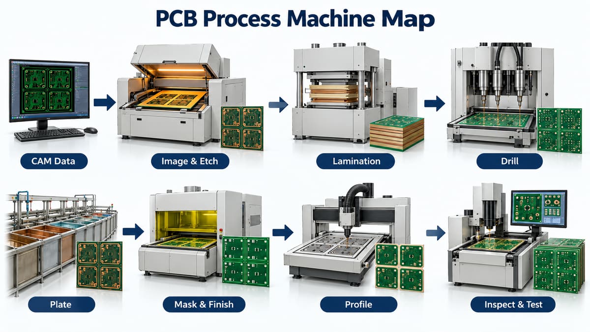
1. CAM and data preparation systems. Engineering software converts Gerbers, drill, profile, netlist, and drawings into machine programs and inspection data. The principal risk is running the wrong revision or interpreting ambiguous inputs; program identity and approval must be traceable.
2. Imaging and wet-process equipment. Laminators apply photoresist, imaging systems transfer the pattern, and develop/etch/strip lines form copper conductors. Exposure, registration, chemistry, spray condition, transport speed, and temperature interact. A high-resolution imager cannot compensate for unstable etching.
3. Inner-layer AOI and registration. AOI compares visible copper with digital reference data before lamination. Registration and target-measurement systems help align layers and drilling. Inspection removes defective work early but must be tied to a defined acceptance and repair policy.
4. Layup and lamination equipment. Clean-room layup tools arrange cores, prepreg, and foil; presses apply the released heat, pressure, and vacuum cycle. Press capacity must be evaluated with material system, panel/loading pattern, thermal uniformity, data capture, and preventive maintenance—not platen size alone.
5. CNC and laser drilling. CNC machines create through and mechanical holes; laser systems form selected microvias and fine features. Tool list, hit count, spindle condition, entry/backer materials, focus, energy, debris removal, and layer registration determine whether the subsequent plating can form a reliable connection.
6. Hole preparation and copper plating. Chemical lines clean and condition hole walls, establish conductivity, and build copper. Pumps, filtration, agitation, rectification, dosing, analysis, and transport all affect results. Machine automation must be supported by bath control and coupon verification.
7. Outer-layer, mask, finish, and legend equipment. Further imaging and plating form outer circuitry; coating/exposure systems apply solder mask; surface-finish lines protect exposed copper; printing systems add identification. Each operation must maintain alignment and cleanliness.
8. Profiling and inspection systems. Routers, V-scoring machines, punches, or lasers create the final geometry. Electrical testers verify continuity/isolation, while AOI/AVI, dimensional machines, microsection preparation, impedance systems, and final inspection answer different questions. One test cannot replace all others.
Which Machine Specifications Actually Matter?
Translate the product requirement into an output metric before reading a brochure. For drilling, for example, useful questions cover finished hole range, panel thickness, stack configuration, positional capability under the actual material, tool management, depth control, debris removal, and measurement correlation. Maximum spindle speed alone does not prove hole quality.
| Specification type | Verify with | Common purchasing mistake |
|---|---|---|
| Feature size/accuracy | Capability study on representative product | Using nominal resolution as process capability |
| Throughput | Real route, changeovers, loading and inspection | Using peak cycle rate as factory output |
| Uniformity | Across-panel and load-position measurements | Checking only average result |
| Repeatability | Multiple lots, tools, operators and maintenance states | Accepting one demonstration panel |
| Data/traceability | Actual recipe, alarm and lot record retrieval | Assuming a network port equals integration |
What Utilities and Factory Controls Do the Machines Need?
Equipment selection must include electrical power, water quality and flow, compressed air, vacuum, exhaust, temperature/humidity, clean handling, chemical storage, waste treatment, floor loading, vibration, fire protection, ESD where applicable, and safe maintenance access. A process can drift when facility conditions move even though the machine reports no fault.
How Are PCB Machines Qualified and Maintained?
Qualification should demonstrate installation, operation, and product-relevant performance. Establish calibrated measurement systems, approved recipes, golden/reference artifacts where useful, preventive-maintenance tasks, consumable life, spare parts, alarm response, and requalification triggers. After major repair or software change, prove the output again before releasing customer lots.
What Machine-Related Failures Affect PCB Quality?
- Wrong artwork, drill, route, or inspection program revision.
- Worn drilling/routing tools and unmanaged consumable life.
- Nonuniform exposure, spray, plating current, press temperature, or fluid flow.
- Dirty optics, nozzles, rollers, tanks, fixtures, or handling surfaces.
- Measurement systems that disagree with production equipment.
- Alarm bypasses or maintenance changes without lot containment.
- Data captured without linking it to panel, coupon, recipe, and time.
How Should a Factory Select PCB Manufacturing Equipment?
- Define the product families and process routes.
- Convert designs into measurable process outputs and acceptance evidence.
- Run representative samples, including worst-case material and panel conditions.
- Assess measurement correlation, utilities, safety, maintenance, parts and support.
- Evaluate changeover and real throughput rather than catalog maximums.
- Validate interfaces, recipe control, alarms, backup and traceability.
- Pilot, qualify, document, train and release through change control.
How Do Buyers Audit a PCB Factory’s Machines?
Follow one real job from data release to final test. Ask operators and engineers to show the approved program, material identity, setup verification, process records, inspection result, nonconformance route, maintenance status, and final report. A machine list is useful context; traceable execution is stronger evidence.
Frequently Asked Questions
Can one machine manufacture a complete PCB?
No. PCB fabrication requires multiple mechanical, chemical, imaging, thermal, and inspection processes linked by controlled data and handling.
Is newer PCB equipment always more capable?
No. Capability depends on configuration, tooling, process stability, measurement, maintenance, materials, and operator/engineering control as well as equipment design.
What is LDI equipment used for?
Laser direct imaging transfers digital pattern data to photoresist without conventional artwork film. Its value still depends on registration, resist, exposure settings, development, and etching.
Why are AOI and electrical test both needed?
AOI examines observable conductor geometry; electrical test checks finished continuity and isolation. They answer different defect questions.
What equipment makes plated through holes?
Drilling creates the hole, chemical preparation exposes and conditions surfaces, and metallization/plating equipment deposits conductive copper. Reliability depends on the whole chain.
How should machine throughput be compared?
Use representative panel size, product mix, changeover, loading, maintenance, inspection, rework, and yield. Peak equipment speed alone overstates usable output.
What records should machines retain?
Retain product/program revision, recipe, actual values, timestamps, alarms, operator/system identity, maintenance state, and links to the lot and inspection results as required.
Does automation guarantee PCB quality?
No. Automation improves repeatability and records only when process limits, inputs, measurement, exception handling, and maintenance are correct.
Request a Process-Route Review
Send your PCB data and acceptance requirements through PCBTRY’s contact page. Ask for the manufacturing route, critical equipment/process controls, inspection plan, and report scope that apply to your construction—not a generic factory machine list.



0 Comments