




PCB thickness tolerance means the allowed difference between the specified board thickness and the finished board thickness after lamination, copper plating, solder mask and surface finish. For buyers, the practical question is not only “what is the tolerance,” but whether the tolerance matches the enclosure, connector height, impedance, stiffness and assembly requirements.
A standard PCB thickness such as 1.6 mm is only the nominal target. The final acceptable range depends on material stackup, layer count, copper weight, plating, solder mask, surface finish and the manufacturer capability. If the tolerance is important to your product, it should be written clearly in the RFQ instead of being assumed.
What PCB Thickness Tolerance Means
PCB thickness tolerance is the acceptable finished thickness range of the complete printed circuit board. If a drawing says 1.6 mm with a tolerance, the manufacturer should deliver boards within that allowed range after all fabrication processes are complete.
Think of it in plain language: the number on the drawing is the target, and the tolerance is the allowed “plus or minus” space around that target. A board may start from cores and prepregs, but buyers normally receive the finished PCB, so the finished-board condition is what matters for fit, assembly and quality inspection.
How Finished PCB Thickness Is Measured
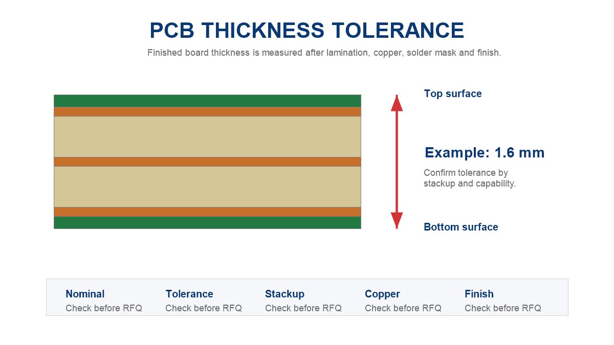
Finished PCB thickness is usually measured from the top finished surface to the bottom finished surface. That includes the laminated structure, copper, plating, solder mask and final surface finish.
Step 1: Confirm whether the drawing asks for total finished board thickness or only dielectric / laminate thickness.
Step 2: Measure on a flat area away from component pads, edge burrs, routed slots and local copper build-up when possible.
Step 3: Compare the measured value with the tolerance stated on the fabrication drawing, purchase order or approved stackup.
Common PCB Thickness Ranges Buyers Should Confirm
Common PCB thickness values are useful references, but they are not a substitute for a controlled requirement. Buyers should confirm the nominal thickness, tolerance and whether the supplier can hold that tolerance for the selected construction.
| Nominal Thickness | Common Use | Buyer Check |
|---|---|---|
| 0.4-0.8 mm | Thin electronics, compact products, flex-rigid areas | Check stiffness, warpage and panel support |
| 1.0-1.2 mm | Space-limited boards, handheld devices | Check connector fit and assembly handling |
| 1.6 mm | Common rigid PCB baseline | Still confirm tolerance and stackup |
| 2.0 mm or above | Higher stiffness, power boards, mechanical support | Check drilling, routing and press capability |
Do not assume that every manufacturer uses the same tolerance for the same nominal number. Two boards can both be called 1.6 mm but have different accepted ranges depending on build method and specification.
Why Thickness Tolerance Changes Between PCB Types
Thickness tolerance changes because different PCB types are built from different materials and processes. A simple two-layer rigid board is not controlled in the same way as an HDI board, heavy copper board, high frequency board or rigid-flex PCB.
| PCB Type | Why Tolerance Can Change | What to Confirm |
|---|---|---|
| Standard FR-4 PCB | Laminate and prepreg variation | Finished thickness range |
| HDI PCB | Thin dielectrics, microvia structures and lamination cycles | Approved stackup and impedance needs |
| Heavy copper PCB | Thicker copper and plating build-up | Copper weight and final thickness |
| High frequency PCB | Material dielectric thickness affects impedance | Material system and controlled impedance |
| Rigid-flex PCB | Rigid and flex zones may have different thicknesses | Zone drawing, bend area and stiffener thickness |
For related material choices, review FR-4 substrate material, copper clad laminate and HDI PCB design considerations before fixing a tight tolerance.
Stackup, Core and Prepreg Decisions That Affect Tolerance
The stackup is often the main reason PCB thickness tolerance cannot be treated as a single simple number. Core thickness, prepreg resin flow, copper layers and lamination pressure all affect the final board thickness.
In a multilayer board, the final thickness is built from several layers, not from one sheet. If the design needs controlled impedance, the dielectric thickness may be more important than the total thickness. If the design needs mechanical fit, the total finished thickness may matter more than each internal dielectric layer.
Before quotation, ask for the proposed stackup if thickness is critical. This lets your engineer confirm whether the board can fit the enclosure, connector, card slot or mating hardware.
Copper Weight, Plating and Surface Finish Effects
Copper weight and plating can add real thickness, especially on heavy copper or high-current boards. Surface finish is thinner than copper plating in many cases, but it still belongs to the finished-board condition.
A heavy copper PCB needs a different thickness discussion from a standard signal board because copper build-up, etching compensation and current-carrying paths all affect manufacturing limits. For high frequency PCB projects, thickness and dielectric control can also affect impedance and signal loss.
When Tight Thickness Tolerance Matters
Tight PCB thickness tolerance matters when the board must fit, mate, bend, carry controlled signals or meet a defined mechanical interface. It does not need to be tightened for every ordinary board.
| Situation | Why It Matters | Buyer Action |
|---|---|---|
| Card-edge connector | Too thick or too thin may affect insertion | State connector requirement |
| Controlled impedance | Dielectric thickness changes impedance | Approve stackup before production |
| Enclosure slot | Mechanical fit may fail | Share enclosure drawing |
| Rigid-flex bend area | Total thickness affects bend stress | Define zone thickness |
| High-current board | Copper build-up changes final thickness | Confirm copper and plating notes |
What to Put in the RFQ Before Quotation
The RFQ should tell the manufacturer exactly which thickness is required and where the tolerance applies. If the RFQ only says “1.6 mm PCB,” the factory may quote against a normal internal standard.
Step 1: State nominal finished PCB thickness, such as 1.6 mm.
Step 2: State the allowed tolerance if it matters, such as “confirm achievable tolerance before production.”
Step 3: Attach Gerber files, drill files, stackup requirement, copper weight, surface finish and fabrication drawing.
Step 4: Mention any mechanical constraint, connector, enclosure, impedance or bend requirement that makes thickness important.
Step 5: Ask the manufacturer to flag conflicts before production, not after panels are built.
How Manufacturers Review Thickness Tolerance for DFM
A manufacturer reviews PCB thickness tolerance by checking whether the requested finished thickness matches the material set, stackup, copper weight, lamination process and inspection method. This is a DFM question, not only a purchasing question.
The engineering review should look for conflicts between total thickness, impedance, copper weight, drill aspect ratio, board size, warpage risk and panelization. If a tighter tolerance increases cost or risk, the supplier should explain what has to change.
How to Check Thickness After Receiving Boards
After receiving boards, check thickness against the approved drawing or stackup, not against memory or an old quote. The acceptance rule should come from the final approved files.
Step 1: Pick several sample boards from the batch.
Step 2: Measure flat locations that are not damaged, burr-heavy or locally unusual.
Step 3: Record each measurement with the tool, location and board revision.
Step 4: Compare results with the approved finished thickness tolerance.
Step 5: If values are out of range, share measurement photos and the original drawing with the supplier before using the boards in assembly.
Common Mistakes That Cause Quote Changes
Most quote changes happen because the thickness requirement was not clear enough at the start. The supplier quotes a normal build, then later discovers that the design needs a tighter stackup or mechanical fit.
- Writing only nominal thickness without tolerance.
- Using old stackup notes from a previous revision.
- Mixing dielectric thickness, core thickness and total finished thickness.
- Forgetting that heavy copper or plating can affect final build.
- Requiring tight tolerance without explaining why.
- Not sharing enclosure, connector or impedance constraints.
PCB Thickness Tolerance Checklist
Use this checklist before sending a PCB thickness tolerance requirement for quotation. It gives the supplier enough information to review feasibility instead of guessing.
| Item | What to Provide | Why It Helps |
|---|---|---|
| Nominal thickness | Finished board thickness target | Sets the baseline |
| Tolerance | Allowed range or request for confirmation | Avoids hidden assumptions |
| Layer count | 2L, 4L, 6L, HDI or other stackup | Controls lamination plan |
| Copper weight | Outer and inner copper requirements | Shows build-up risk |
| Surface finish | ENIG, HASL, OSP or other finish | Defines final condition |
| Mechanical need | Connector, enclosure, slot or fixture | Explains why tolerance matters |
| Inspection request | How thickness should be checked | Aligns acceptance method |
FAQs About PCB Thickness Tolerance
What is PCB thickness tolerance?
It is the allowed variation between the specified PCB thickness and the finished board thickness. It should be judged against the approved drawing, stackup or purchase requirement.
Is 1.6 mm always the final PCB thickness?
No. 1.6 mm is a common nominal thickness, but the delivered board may have an allowed tolerance. Confirm the finished thickness range before ordering.
Does copper weight affect PCB thickness?
Yes. Copper weight, copper plating and process compensation can affect the final board build, especially on heavy copper and high-current boards.
What files help a supplier quote thickness tolerance correctly?
Gerber files, drill files, fabrication drawing, stackup notes, copper weight, surface finish and mechanical constraints help the supplier review the requirement.
Can I request tighter PCB thickness tolerance?
Yes, but the manufacturer must confirm feasibility. Tighter tolerance may affect material selection, lamination control, cost and lead time.
Why does thickness tolerance matter for card-edge connectors?
The board must fit the connector slot. If the board is too thick or too thin, insertion, contact pressure or reliability may be affected.
Does PCB thickness tolerance affect impedance?
Total board thickness may not always control impedance, but dielectric thickness and stackup do. For controlled impedance boards, confirm the stackup with the manufacturer.
How should I inspect received boards?
Measure several flat locations, record the values and compare them with the approved finished thickness tolerance. Avoid measuring damaged edges or local burrs.
Will tight tolerance increase lead time?
It can. If the tolerance requires special material, tighter lamination control or extra inspection, the supplier may need more review time.
What should I ask before sending an RFQ?
Ask whether the requested finished thickness and tolerance are achievable with your material, layer count, copper weight, surface finish and production quantity.
Send PCB Thickness Requirements for Engineering Review
If PCB thickness tolerance affects your enclosure, connector, impedance, stiffness or assembly plan, send your Gerber files, stackup notes, copper weight, surface finish and tolerance requirement to [email protected]. PCBTRY can review the requirement before quotation and point out thickness, material or DFM risks before production starts.



0 Comments